Multi-floating-body sea wave two-stage conversion power-generating device

A power generation device and ocean wave technology, applied in ocean energy power generation, engine components, machines/engines, etc., can solve problems such as low reliability, inability of power generation systems to well apply wave energy development and utilization, weak storm resistance, etc., to achieve Reduce manufacturing and maintenance costs, facilitate large-scale production and utilization, and improve energy conversion efficiency

Active Publication Date: 2018-06-29
SICHUAN UNIV
View PDF4 Cites 6 Cited by
  • Summary
  • Abstract
  • Description
  • Claims
  • Application Information

AI Technical Summary

Problems solved by technology

First, the traditional wave energy power generation system is based on the existing rotating generator. Its high-speed and high-efficiency characteristics do not match the wave energy, forcing the system to use a complex intermediate conversion system, resulting in low efficiency, large structure, and low reliability of the power generation system. Low-level problems have seriously affected the practical application of the technology
Second, traditional wave power generation systems are mostly shore-mounted fixed installations, with high construction costs, long periods, severe environmental constraints, and weak storm resistance
Third, the current wave energy power generation technology mainly comes from countries such as Europe, where the average wave energy density can reach 20-70 kW / m, while the average wave energy density along the coast of my country is 2-7 kW / m. It is very large, and most power generation systems cannot be well applied to the development and utilization of wave energy in my country

Method used


Image

  • Multi-floating-body sea wave two-stage conversion power-generating device
  • Multi-floating-body sea wave two-stage conversion power-generating device
  • Multi-floating-body sea wave two-stage conversion power-generating device

Examples


Embodiment 1

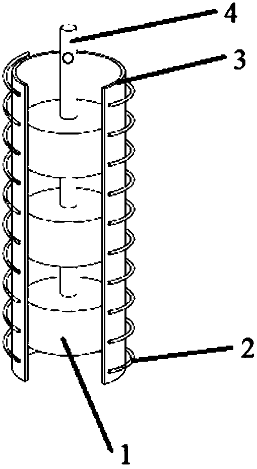
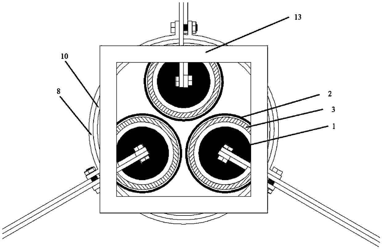
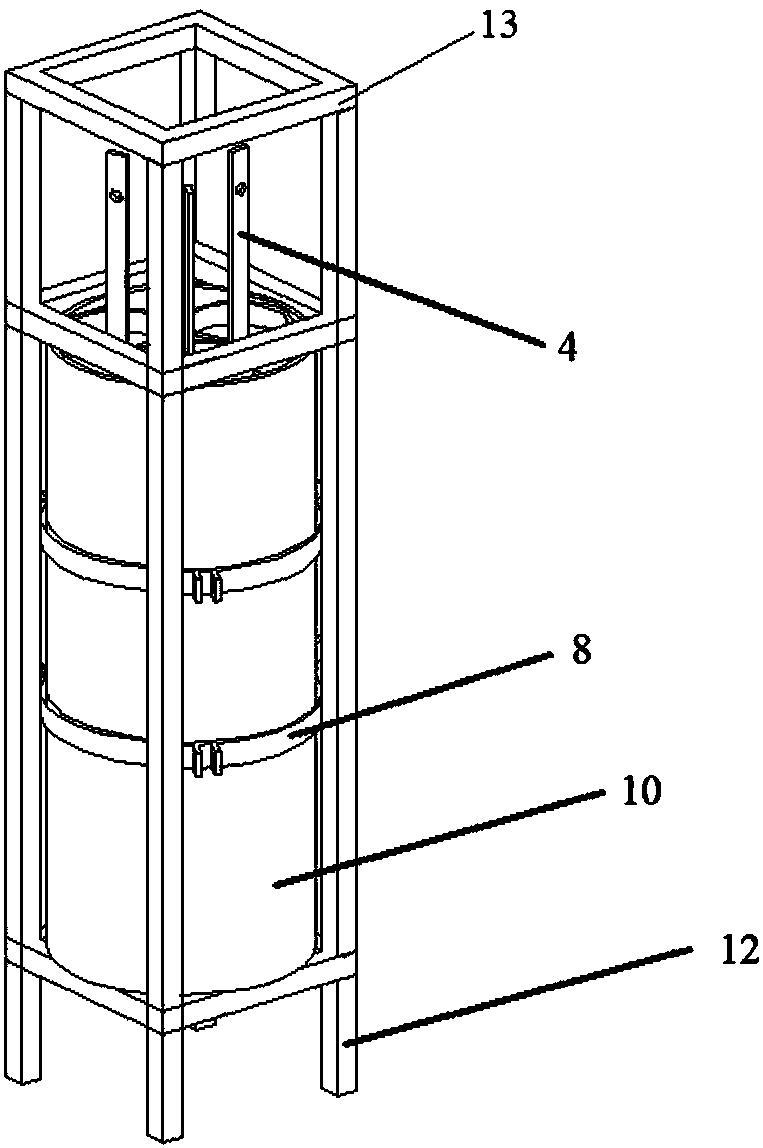
[0036] This embodiment is a multi-floating body wave secondary conversion power generation device with three power generation units, the structure is as follows Figure 1-6 As shown, it is composed of wave direct drive power generation part, power transmission mechanical part, foam buoy 11 and support frame 12. The wave direct drive power generation part is composed of three power generation units and cylindrical anti-corrosion plastic power generation bucket 10. The power transmission mechanical part Three groups of floats are correspondingly arranged corresponding to the generating units. Each power generation unit is composed of three cylindrical NdFeB strong magnet blocks 1 fixed in series on the same magnet connecting rod 4 at equal intervals to form a mover, and a copper coil 2 spirally wound on a plastic coil cylinder 3 to form a mover. Stator composition. The three coil cylinders wound with copper coils are placed upright and the lower end is fixed on the bottom of th...


PUM


Abstract

The invention provides a multi-floating-body sea wave two-stage conversion power-generating device, which comprises a sea wave direct-drive power-generating part, force transmitting mechanical parts,floaters and a support frame, wherein the sea wave direct-drive power-generating part is composed of at least one generating unit and a generating barrel; each generating unit is composed of a rotor formed by Rb-Fe-B strong magnets which are equidistantly fixed on the same magnet connecting rod in series connection and a stator formed by spirally winding a coil on a coil cylinder; the coil cylinders are vertically placed, and the lower ends of the coil cylinders are fixed at the bottom of the generating barrel; each rotor is positioned in an inner space of the corresponding coil cylinder; andeach force transmitting mechanical part is composed of a transmitting rod with one end being movably connected with the top end of the magnet connecting rod and the other end being movably connected with the corresponding floater, an upper fixing ring and a lower fixing ring which are matched with the outer diameter of the generating barrel and are fixed on different heights of the generating barrel, a short supporting rod with one end being movably connected with the upper fixing ring, and a long supporting rod with one end being movably connected with the lower fixing ring. The device has the characteristics of flexible arrangement, simple structure, low cost and high operation efficiency.

Description

technical field [0001] The invention belongs to the field of ocean energy power generation, in particular to an ocean wave conversion power generation device. Background technique [0002] Wave energy is the most widely distributed and abundant renewable energy in the ocean, and the wave energy that can be developed and utilized in the world reaches 2 billion kilowatts. my country's ocean wave energy resources are relatively rich in reserves, with a theoretical reserve of 12.84 million kilowatts, which has broad prospects for development and utilization. In traditional wave power generation systems, rotary generators are used without exception. Since wave energy exists in the form of high-force, low-speed reciprocating motion, to couple this energy system with a high-speed rotating generator, a series of energy conversion and speed change devices must be used. The traditional wave energy power generation system generally consists of three parts, namely wave collection syst...

Claims


Application Information

Patent Timeline
Patent Type & Authority Applications(China)
IPC IPC(8): F03B13/20
CPCF03B13/20Y02E10/30
Inventor 罗铭黄尔路信丁锐于合理王之晗官夏菲
Owner SICHUAN UNIV
Why Eureka
Try Eureka