Eureka AIR delivers breakthrough ideas for toughest innovation challenges, trusted by R&D personnel around the world.

Glass single-side thinning method and glass thinning equipment

A glass thinning and equipment technology, applied in the field of glass single-sided thinning method and glass thinning equipment, can solve the problems of affecting the thinning quality, uneven glass thinning, uneven etching, etc., to avoid uneven thinning treatment Uniformity, wide processing range and wide application range

Active Publication Date: 2022-04-26
凯盛科技股份有限公司
View PDF21 Cites 0 Cited by
  • Summary
  • Abstract
  • Description
  • Claims
  • Application Information

AI Technical Summary

Problems solved by technology

[0004] However, there are still obvious defects in its use: 1. The above-mentioned device adopts the method of moving the glass into the etching tank for thinning treatment, but in the process of thinning treatment, the etching solution will continue to decrease, resulting in liquid level In order to achieve the predetermined thinning thickness, it is necessary to continuously adjust the position of the glass, and there may be bubbles in the etching solution, which makes the thinning of the glass uneven and affects the quality of thinning; Placed in the etching tank, the glass will produce impurities during the thinning process. If the glass is placed horizontally, in order to protect the non-thinning surface of the glass, the etching solution needs to be relatively stable, so the dirt is easy to adhere to the thinning surface of the glass, resulting in etching. Impurities are difficult to remove, and the problem of reverse wear on the glass. If the glass is placed vertically, the etching solution that touches the upper glass will touch the lower glass again during the sliding process, resulting in uneven etching. Both have disadvantages

Method used


Image

  • Glass single-side thinning method and glass thinning equipment
  • Glass single-side thinning method and glass thinning equipment
  • Glass single-side thinning method and glass thinning equipment

Examples


Embodiment 1

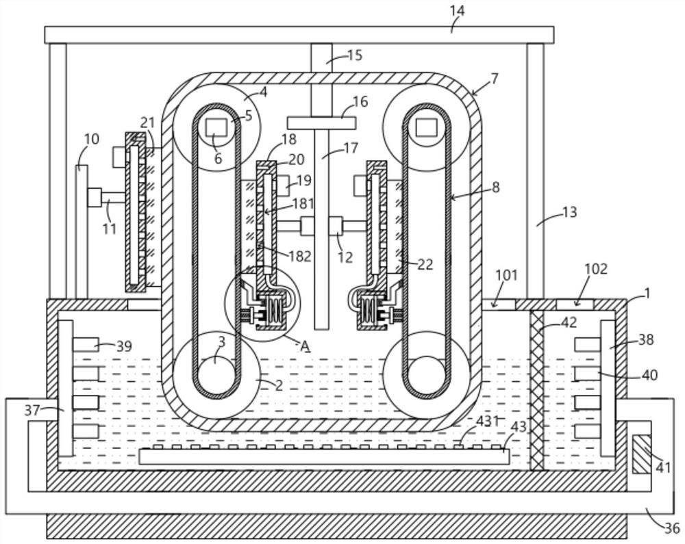
[0038] A glass thinning device, comprising a box body 1, the top of the box body 1 is provided with an operation port 101, the first water-absorbing transmission belt 7 and its internal structure are all arranged in the operation port 101, and the inner cavity of the box body 1 is symmetrically hinged. There is a lower external gear 2, the center of the lower external gear 2 is fixedly provided with a lower internal gear 3, the upper part of the lower external gear 2 is vertically provided with an upper external gear 4, and the center of the upper external gear 4 is fixedly provided with an upper internal gear 5, In this embodiment, the diameter of the lower external gear 2 is greater than the diameter of the lower internal gear 3, the diameter of the upper external gear 4 is greater than the diameter of the upper internal gear 5, and the upper internal gear 5 can be driven to rotate by the driving motor 6. In this embodiment , the drive motor 6 is a motor that can rotate in bo...

Embodiment 2

[0042] On the basis of Embodiment 1, this embodiment further defines and discloses the specific structure of the support device: the support device includes uprights 13, and there are two uprights 13 fixedly arranged on the top of the box body 1, the uprights 13 An integrated horizontal plate 14 is fixedly arranged on the top, an extension plate 15 is fixedly arranged below the horizontal plate 14, and an installation platform 16 is fixedly arranged below the extension plate 15. The installation platform 16 has a large area and is located on the second water-absorbing transmission belt 8 In the enclosed area, the bottom of the installation platform 16 is fixedly provided with a bearing plate 17, and the non-piston rod ends of the second cylinder 12 are all fixedly arranged on the bearing plate 17, where the two second cylinders 12 are arranged oppositely, and can Independent control, so the glass can be thinned according to different requirements. The side of the adsorption pla...

Embodiment 3

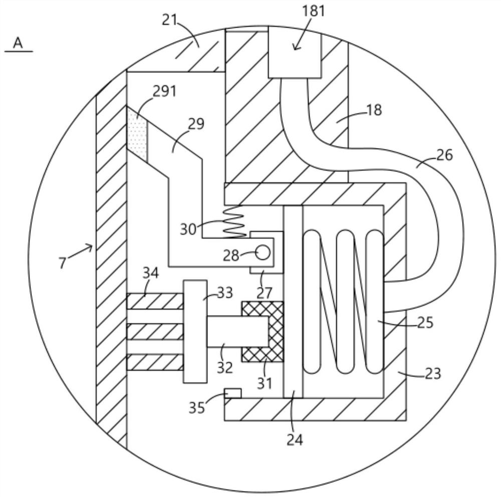
[0044] On the basis of Embodiment 1, this embodiment further defines and discloses the specific structure of the dust scraping device: the dust scraping device includes a base block 27, on which a rotating shaft 28 is fixedly arranged, and on the rotating shaft 28 is hingedly arranged There is a scraper 29, and the end of the scraper 29 away from the rotating shaft 28 is provided with a silica gel segment 291. The quality of the silica gel segment 291 is softer, which can avoid damage to the second water-absorbing transmission belt 8 in the process of scraping off impurities. The scraper 29 and the operation A compression spring 30 is connected between the inner walls of the frame 23, so that the scraper 29 can rotate around the rotating shaft 28 in a small range, and its function is to further protect the second water-absorbing transmission belt 8 from being scratched and damaged.


PUM


Abstract

The invention provides a glass single-face thinning method and glass thinning device.The glass single-face thinning device comprises a box body, an air cavity and an adsorption hole which are communicated are formed in an adsorption plate, a vacuum pump is fixedly arranged on the outer side of the adsorption plate and communicates with the air cavity, and the adsorption plate close to a first air cylinder is used for adsorbing a first glass plate; the adsorption plate close to the second air cylinder is used for adsorbing a second glass plate, a dust scraping device and a scrubbing device are arranged on the side, away from the reset spring, of the piston plate, a scraping plate in the dust scraping device can make movable contact with the first water absorption transmission belt, and a brush in the scrubbing device can make rotary contact with the first water absorption transmission belt. The invention provides a glass single-side thinning method and glass thinning equipment, which can simultaneously carry out thinning treatment on glass with different sizes, do not need to frequently adjust the position of the glass according to the height of the liquid level of etching liquid, also avoid the problem of uneven etching caused by bubbles in the etching liquid, and have a wider application range.

Description

technical field [0001] The invention relates to the technical field of glass thinning, in particular to a glass single-sided thinning method and glass thinning equipment. Background technique [0002] At present, the method of single-sided etching of the glass substrate is mainly: attach the acid-resistant film to the surface of the glass substrate that needs to be protected, and use an etching device to etch the treated glass substrate. After the treatment is completed, the acid-resistant film is protected. Peel off to achieve the effect of single-sided etching. [0003] In the prior art, the publication number is "CN106746705A", a glass single-sided thinning method and glass thinning equipment, the method includes the following steps: S1, the glass is detachably fixed on the fixed surface of the acrylic plate, and the glass The acid-resistant film faces the fixed surface of the acrylic plate; S2, moves the acrylic plate with the glass fixed into the etching tank to thin t...

Claims


Application Information

Patent Timeline
Patent Type & Authority Applications(China)
IPC IPC(8): C03C15/00
CPCC03C15/00Y02P40/57
Inventor 夏宁倪植森陈诚黄迎辉樊黎虎巩燕龙胡克军邵帅杨波李若尘
Owner 凯盛科技股份有限公司
Why Eureka
Eureka Blog
Learn More