Nerve interface
An interface and neural technology, applied in the field of neural interface, can solve the problem that the substrate of the neural interface cannot be attached well
- Summary
- Abstract
- Description
- Claims
- Application Information
AI Technical Summary
Problems solved by technology
Method used
Image
Examples
Embodiment 1
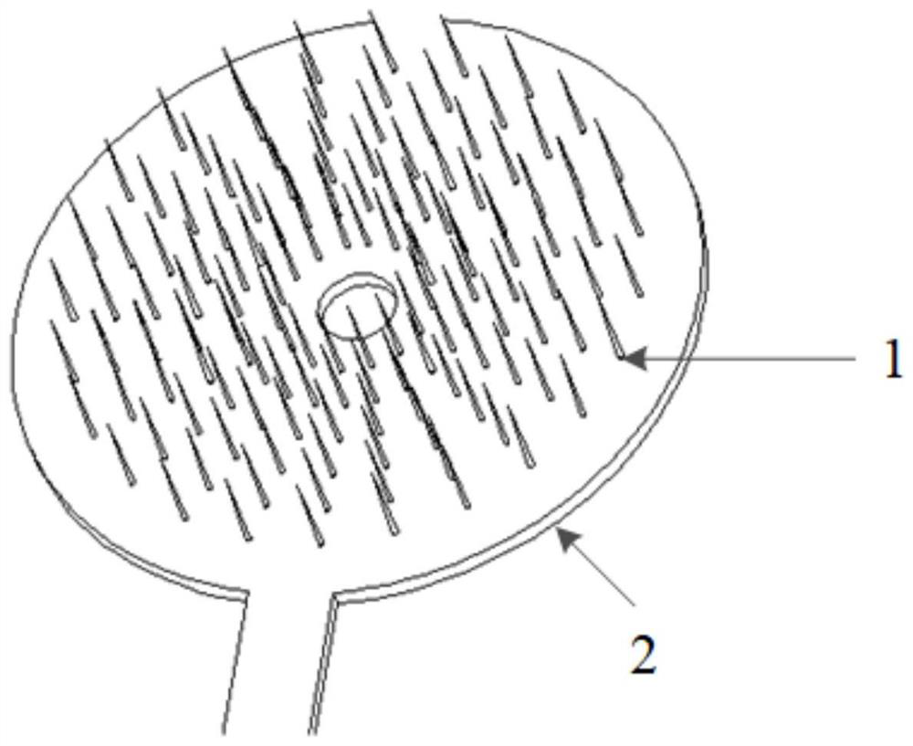
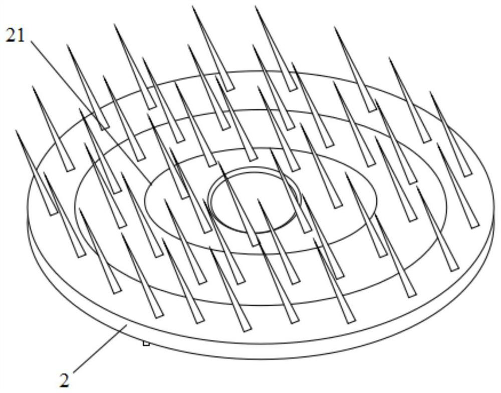
[0030] combine figure 1 and figure 2 , the present embodiment provides a neural interface, which includes at least one microneedle body 1 and a flexible base 2, and the microneedle body 1 is bound on the flexible base 2. Wherein, at least one body electrode point is arranged on the microneedle body 1, and the body electrode point is used for collecting nerve signals.
[0031] Wherein, the flexible substrate 2 is made of flexible materials, wherein the flexible materials include silica gel, PDMS, polyimide or bacterial cellulose.
[0032] In an optional embodiment, the flexible base 2 has a hollowed out part to improve the flexibility of the flexible base 2 .
[0033] In this embodiment, the flexible base 2 is circular, elliptical, polygonal or fan-shaped.
[0034] In an actual application scenario, the number of the microneedles 1 is multiple, and the plurality of microneedles 1 are arranged and formed along a preset rule to form a microneedle array on the flexible substra...
Embodiment 2
[0042] Such as figure 1 As shown, the present application provides a neural interface, including at least one microneedle body 1 and a flexible base 2, and the microneedle body 1 is bound on the flexible base 2.
[0043] In an optional embodiment, the flexible substrate 2 is disc-shaped, and when there are a plurality of microneedles 1, the plurality of microneedles 1 can be arranged along the diameter of the disc to form a microneedle array, Wherein, along the direction away from the geometric center of the flexible substrate, the distribution of the microneedles 1 is gradually sparse. Since the flexible base 2 is made of flexible materials, the flexible base 2 can be deformed. In the actual use process, an external force can be applied to the flexible base according to the specific structure of the target position, so that the flexible base is deformed to ensure that the flexible base and the target position are formed. Good attachment can increase the implantation depth of...
Embodiment 3
[0050] In this embodiment, the application provides another neural interface, which can be used as an artificial retina to enable people with retinal damage or detachment to have visual perception function. The artificial retinal microneedle array structure made of flexible substrate 2 does not need to order the binding material of the microneedle body 1 according to the size of the eyeballs of the visually impaired in advance. The flexible substrate 2 is easy to deform, which can make the microneedle The body 1 is inserted into the nerve tissue of the retina, making the back of the flexible base 2 concave to form a hemispherical shape, forming a good fit with the eyeball, and reducing the friction sensation caused by the rigid binding material.
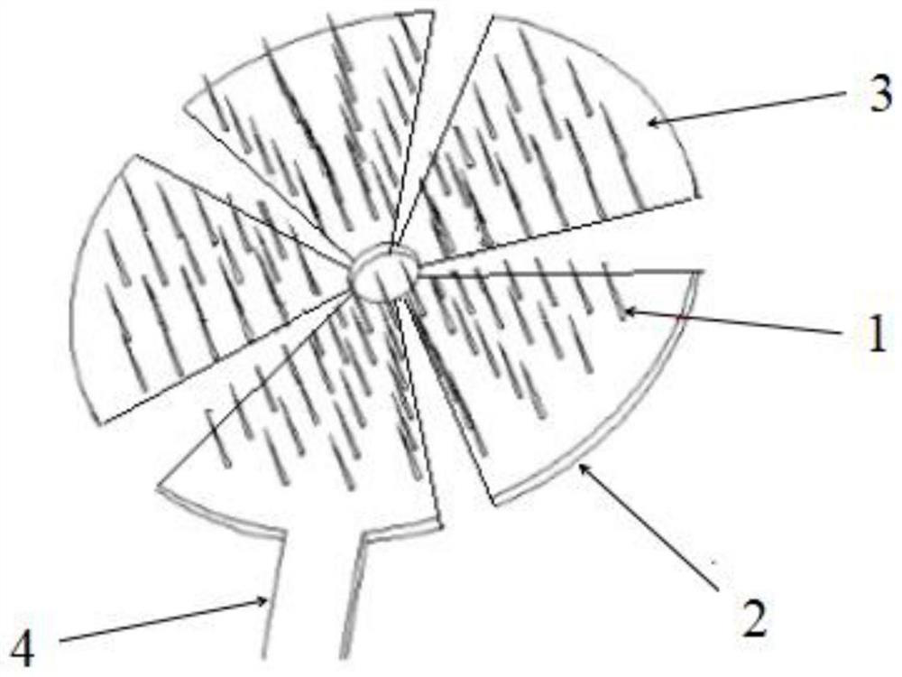
[0051] In one of the optional embodiments, the disc-shaped flexible base 2 has a hollowed out part, that is, a part that does not need to bind the microneedle body 1, and the hollowed out part can be set according to the structure of ...
PUM
 Abstract
Description
Claims
Application Information
 - R&D
- Intellectual Property
- Life Sciences
- Materials
- Tech Scout
- Unparalleled Data Quality
- Higher Quality Content
- 60% Fewer Hallucinations
Browse by: Latest US Patents, China's latest patents, Technical Efficacy Thesaurus, Application Domain, Technology Topic, Popular Technical Reports.
© 2025 PatSnap. All rights reserved.Legal|Privacy policy|Modern Slavery Act Transparency Statement|Sitemap|About US| Contact US: help@patsnap.com


