Locking device for roller bearing seat of pipe mill

A roll bearing and locking device technology, which is applied in the direction of metal rolling mill stands, metal rolling racks, metal rolling, etc., can solve problems such as broken output rods of hydraulic cylinders, inability to replace hydraulic cylinders, and potential safety hazards in production. Achieve the effect of preventing breakage, low maintenance cost, and reduced maintenance cost

Active Publication Date: 2022-04-29
DAYE SPECIAL STEEL CO LTD
View PDF7 Cites 0 Cited by
  • Summary
  • Abstract
  • Description
  • Claims
  • Application Information

AI Technical Summary

Problems solved by technology

The locking block of the roll bearing seat often rotates (partly because there is no anti-rotation function designed between the locking block and the bearing seat, and the other part is because the output rod of the hydraulic cylinder is not equipped with an anti-rotation function), which may easily cause the roll Disengagement will cause equipment failure and hidden dangers in production safety: the disengagement of the roll will easily cause the output rod of the hydraulic cylinder to break, and the locking block and the output rod of the hydraulic cylinder will be integrated into one body, and the total length is greater than that between the roll bearing seat and the drum. The maximum distance, resulting in the inability to replace the hydraulic cylinder as a whole online, requires a long shutdown, maintenance is time-consuming and labor-intensive, and affects production

Method used


Image

  • Locking device for roller bearing seat of pipe mill
  • Locking device for roller bearing seat of pipe mill
  • Locking device for roller bearing seat of pipe mill

Examples


Embodiment Construction

[0042] The present application will be described in detail below with reference to the accompanying drawings and embodiments. Each example is provided by way of explanation of the application, not limitation of the application. In fact, those skilled in the art will recognize that modifications and variations can be made in the present application without departing from the scope or spirit of the application. For example, features illustrated or described as part of one embodiment can be used on another embodiment to yield a still further embodiment. Accordingly, it is intended that the present application cover such modifications and variations as come within the scope of the appended claims and their equivalents.

[0043]In the description of this application, the terms "vertical", "transverse", "upper", "lower", "front", "rear", "left", "right", "vertical", "horizontal", " The orientation or positional relationship indicated by "top", "bottom", etc. is based on the orient...


PUM


Abstract

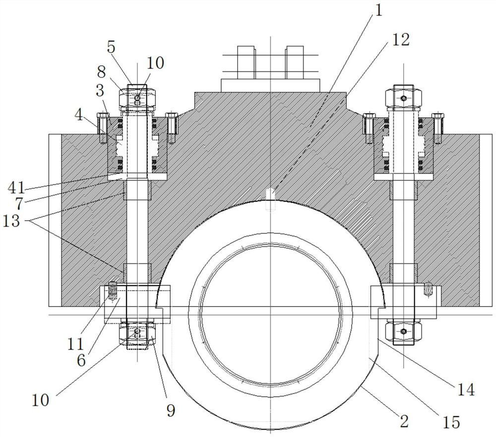
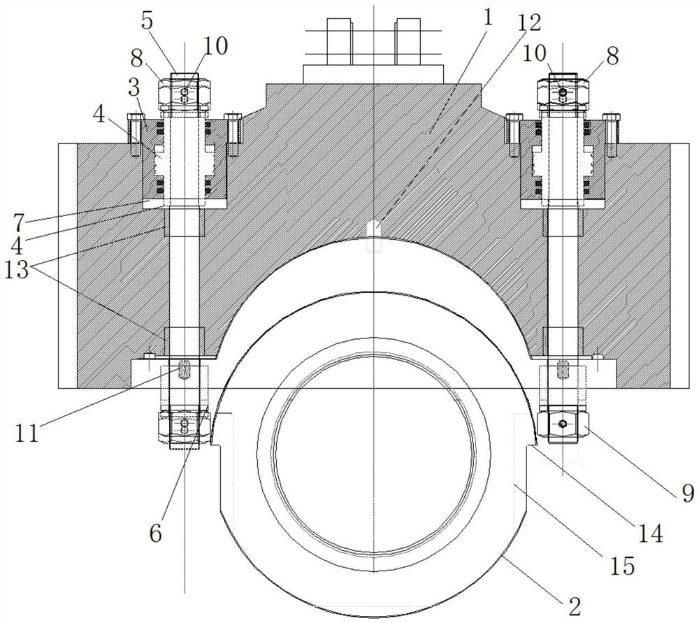
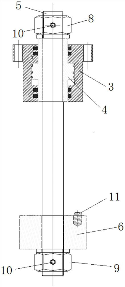
The invention relates to the technical field of rolling equipment, in particular to a locking device for a roller bearing seat of a pipe mill. The locking device for the roller bearing seat of the pipe mill is used for locking the roller bearing seat, and comprises a base, a locking device, a locking device and a locking device, and the base is provided with a bearing seat accommodating groove and two through holes; cylinder bodies of the two hydraulic cylinders are fixed to the base and located at the tops of the two through holes respectively, output rods of the hydraulic cylinders penetrate through the through holes and stretch out of the bottom ends of the through holes, and locking blocks are arranged on the stretching-out parts; the roller bearing seat is arranged on the roller bearing in a sleeving mode and embedded into the bearing seat containing groove, two step faces are oppositely arranged on the peripheral face of the roller bearing seat, each step face is formed by a first plane and a second plane, and the first plane is perpendicular to the axis of the through hole; when the output rods of the hydraulic cylinders are located at the upper end of the moving stroke, the locking blocks are driven to be pressed on the corresponding first planes, the two locking blocks are matched, and the roller bearing seat is pressed and fixed in the bearing seat containing groove.

Description

technical field [0001] The present application relates to the technical field of rolling equipment, in particular to a locking device for a roll chock of a pipe rolling mill. Background technique [0002] During the rolling process of existing pipe mills, due to the axial movement of the rolls, on the one hand, the axial load on the bearings equipped with the rolls is increased, resulting in shortened service life of the bearings; The alternating stress between the roll surface and the blank causes the fatigue of the roll surface and affects the surface quality of the blank. [0003] The main function of the locking block is to lock the bearing seat of the roll to prevent the axial movement of the roll. Specifically, the locking block is arranged on the operating side of the rolling mill stand and fixed on the front end of the hydraulic cylinder. When the hydraulic cylinder is in motion, the piston rod pushes the locking block so that it snaps into the roll chock and locks ...

Claims


Application Information

Patent Timeline
Patent Type & Authority Applications(China)
IPC IPC(8): B21B31/07B21B31/02B21B31/08
CPCB21B31/07B21B31/02B21B31/08Y02P70/10
Inventor 程卫国邹应东张红军
Owner DAYE SPECIAL STEEL CO LTD
Why Eureka
Try Eureka