Oil smoke removing device of cold header

A technology of oil fume device and cold heading machine, which is applied in the direction of operation device, dust removal, forging/pressing/hammer device, etc., which can solve the problems of accumulated oil fume, machine damage, large oil fume, etc., and achieve the effect of increasing resistance and promoting shaking off Effect

Inactive Publication Date: 2022-04-29
诸玲敏
View PDF0 Cites 0 Cited by
  • Summary
  • Abstract
  • Description
  • Claims
  • Application Information

AI Technical Summary

Problems solved by technology

[0003] A large amount of oil is used in the working process of the cold heading machine, and the temperature is too high during operation, especially at the discharge port of the cold heading machine, there is a lot of oily smoke. It is extremely inconvenient for employees to inspect products, maintain machines and replace material barrels. It will also accumulate a lot of oil fume, which is easy to cause damage to the machine and endanger the health of the staff. Therefore, a corresponding improvement is made to solve this problem, and a cold heading machine oil fume removal device is proposed

Method used


Image

  • Oil smoke removing device of cold header
  • Oil smoke removing device of cold header
  • Oil smoke removing device of cold header

Examples


Embodiment 1

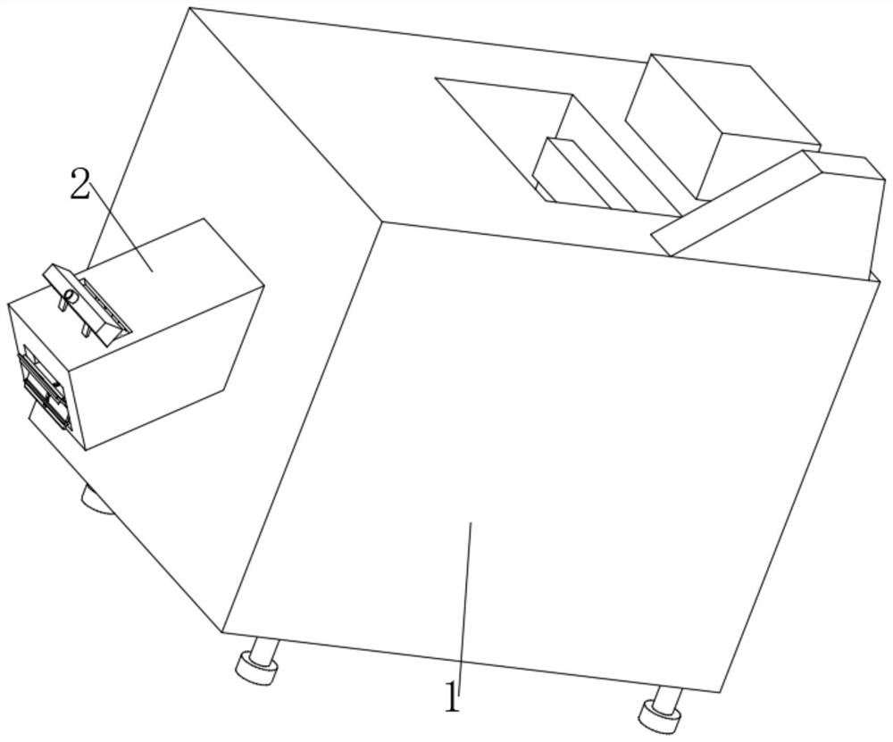
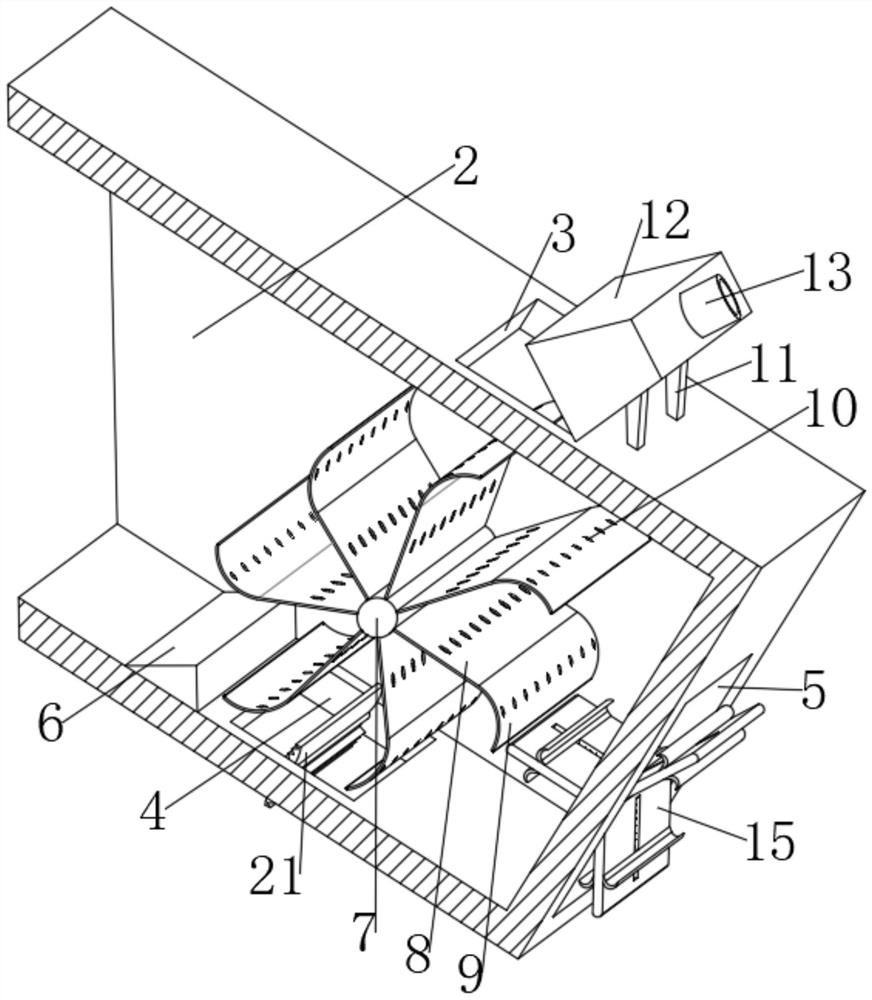
[0032] refer to Figure 1-2 and Figure 4-6 , a cold heading machine oil fume removal device, including a cold heading machine body 1, a discharge channel 2 is fixed by bolts at the outlet of the cold heading machine body 1, and the discharge channel 2 is inclined to the side away from the cold heading machine body 1 Next, the top of the discharge channel 2 is provided with an air outlet 3, the bottom of the discharge channel 2 is provided with an air inlet 4, and the side of the discharge channel 2 away from the cold heading machine body 1 is provided with a discharge port 5. The discharge channel 2 The inner wall of the bottom is fixed with a jump-helping block 6 by bolts. To the mechanism, the discharge port 5 is provided with a discharge aid mechanism, and the discharge channel 2 is provided with an oil filter mechanism.

[0033] Further, the smoking mechanism includes a fume suction head 12, two symmetrically distributed ribs 11 are fixed on the top of the discharge cha...

Embodiment 2

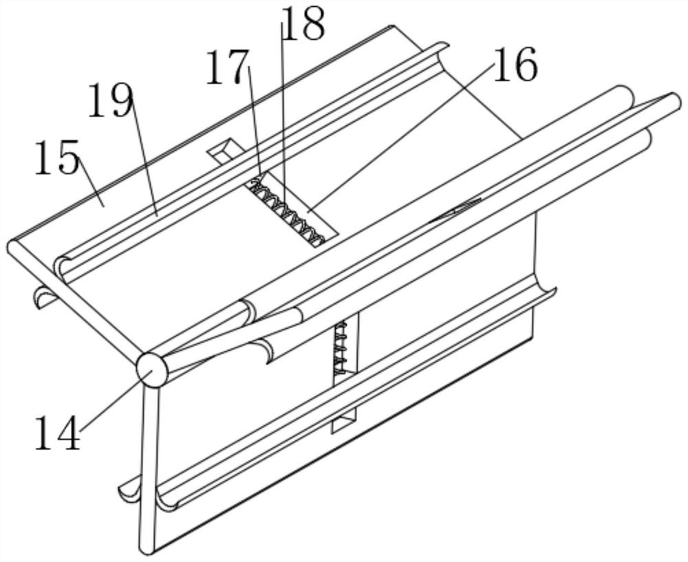
[0042] refer to Figure 1-2 , Figure 4-5 and Figure 7-8 , a cold heading machine oil fume removal device, including a cold heading machine body 1, a discharge channel 2 is fixed by bolts at the outlet of the cold heading machine body 1, and the discharge channel 2 is inclined to the side away from the cold heading machine body 1 Next, the top of the discharge channel 2 is provided with an air outlet 3, the bottom of the discharge channel 2 is provided with an air inlet 4, and the side of the discharge channel 2 away from the cold heading machine body 1 is provided with a discharge port 5. The discharge channel 2 The inner wall of the bottom is fixed with a jump-helping block 6 by bolts. To the mechanism, the discharge port 5 is provided with a discharge aid mechanism, and the discharge channel 2 is provided with an oil filter mechanism.

[0043] Further, the smoking mechanism includes a fume suction head 12, two symmetrically distributed ribs 11 are fixed on the top of th...

Embodiment 3

[0052] refer to Figure 1-5 and Figure 7-8 , a cold heading machine oil fume removal device, including a cold heading machine body 1, a discharge channel 2 is fixed by bolts at the outlet of the cold heading machine body 1, and the discharge channel 2 is inclined to the side away from the cold heading machine body 1 Next, the top of the discharge channel 2 is provided with an air outlet 3, the bottom of the discharge channel 2 is provided with an air inlet 4, and the side of the discharge channel 2 away from the cold heading machine body 1 is provided with a discharge port 5. The discharge channel 2 The inner wall of the bottom is fixed with a jump-helping block 6 by bolts. To the mechanism, the discharge port 5 is provided with a discharge aid mechanism, and the discharge channel 2 is provided with an oil filter mechanism.

[0053] Further, the smoking mechanism includes a fume suction head 12, two symmetrically distributed ribs 11 are fixed on the top of the discharge cha...


PUM


Abstract

The invention belongs to the technical field of cold headers, and particularly relates to a cold header oil fume removing device which comprises a cold header body, a discharging channel is fixed to the discharging position of the cold header body through bolts, the side, away from the cold header body, of the discharging channel inclines downwards, and an air outlet is formed in the top of the discharging channel in a penetrating mode. An air inlet is formed in the bottom of the discharging channel in a penetrating mode, a discharging port is formed in the side, away from the cold header body, of the discharging channel in a penetrating mode, a jumping assisting block is fixed to the inner wall of the bottom of the discharging channel through bolts, the section of the jumping assisting block is arranged to be triangular, and the jumping assisting block is arranged above the air inlet. A turning mechanism is arranged in the air inlet, a discharging assisting mechanism is arranged in the discharging port, and an oil filtering mechanism is arranged in the discharging channel. According to the device, when the workpieces are discharged, engine oil is shaken off, so that the dual effects of sucking and discharging oil smoke and separating the engine oil adhered to the workpieces are achieved.

Description

technical field [0001] The invention relates to the technical field of cold heading machines, in particular to an oil fume removal device for cold heading machines. Background technique [0002] The cold heading machine is mainly pier, which is specially used for mass production of fasteners such as nuts and bolts. The cold heading process is based on the theory of metal plastic deformation, and a certain pressure is applied to the metal blank at room temperature to make it in the mold cavity. Plastic deformation is generated inside, and it is formed according to the specified shape and size. The products produced by the cold heading process have better surface quality and higher dimensional accuracy. The cold heading process is suitable for products with large batches and various specifications. [0003] A large amount of oil is used in the working process of the cold heading machine, and the temperature is too high during operation, especially at the discharge port of the ...

Claims


Application Information

Patent Timeline
Patent Type & Authority Applications(China)
IPC IPC(8): B21K27/00B08B7/02B08B15/04
CPCB21K27/00B08B7/02B08B15/04
Inventor 诸玲敏
Owner 诸玲敏
Why Eureka
Try Eureka