
Movable anti-seismic power transmission tower

A transmission tower and movable technology, applied in the field of transmission towers, can solve the problems of weak seismic resistance, unstable installation, and easy deformation of transmission towers, and achieve the effects of shortening transportation time, facilitating transportation, and reducing vibration amplitude.

Pending Publication Date: 2022-04-29
邱文清
View PDF0 Cites 0 Cited by
  • Summary
  • Abstract
  • Description
  • Claims
  • Application Information

AI Technical Summary

Problems solved by technology

[0005] The present invention provides a movable anti-seismic power transmission tower, one of which is to have anti-seismic and deformation correction functions, to solve the problem of easy tilting and deformation, and the weak anti-seismic ability of the power transmission tower; the other purpose is to Solve the problems of inconvenient handling and unstable installation to achieve efficient operation

Method used


Image

  • Movable anti-seismic power transmission tower
  • Movable anti-seismic power transmission tower
  • Movable anti-seismic power transmission tower

Examples


Embodiment 1

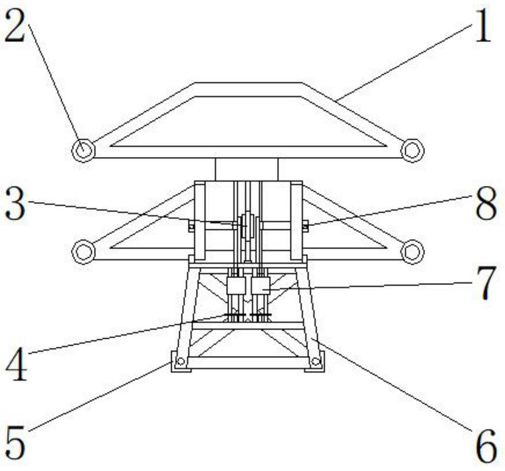
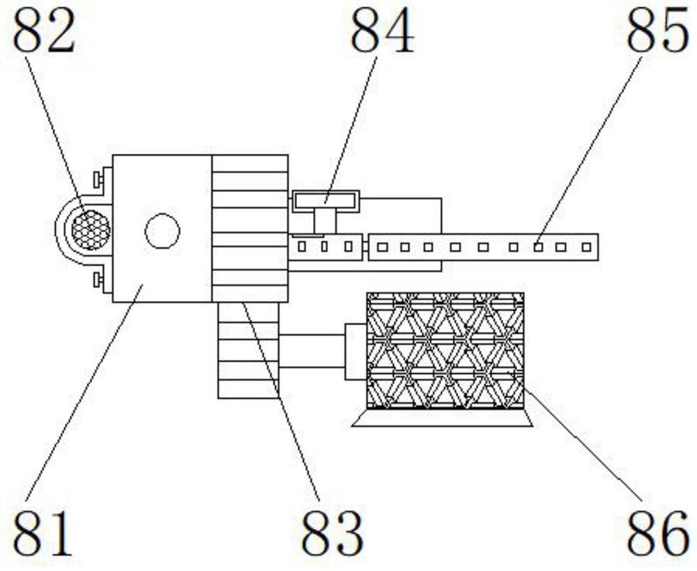
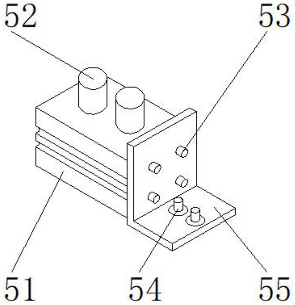
[0030] Such as Figure 1-6 As shown, the present invention provides a movable anti-seismic power transmission tower, comprising a main body 1, connecting bolts 2 are arranged on both sides of the main body 1, an anti-seismic device 3 is arranged under the main body 1, and deformation correction devices are arranged on both sides of the anti-seismic device 3 Device 8, a contraction device 7 is provided below the anti-seismic device 3, and the lower end of the contraction device 7 is provided with an elastic member 4, and the two sides of the elastic member 4 are provided with a support frame 6, and the lower end of the support frame 6 is provided with a stabilizing device 5; the stabilizing device 5 includes a metal weight block 51, a connecting column 52, a bolt 53, a reinforcing rib 54, and an L-shaped plate 55. The connecting column 52 is located at the upper end of the metal weighted block 51, and the L-shaped plate 55 is located at one side of the metal weighted block 51; t...

Embodiment 2

[0033] Such as Figure 1-6 As shown, on the basis of Embodiment 1, the present invention provides a technical solution: preferably, the anti-seismic device 3 includes a buffer frame 31, a sliding block 32, a counterweight 33, a spring column 34, a placement block 35, and a spring column 34 Through the buffer frame 31, the counterweight 33 is located at the two ends of the buffer frame 31, the sliding block 32 is located at the lower end of the spring post 34, the placement block 35 is located at the upper end of the spring post 34, and the buffer frame 31 and the counterweight 33 are provided with Notch, the two ends of the buffer frame 31 are detachably connected with the upper end of the counterweight 33 through the notch, a threaded groove is provided between the spring post 34 and the sliding block 32, and the lower end of the spring post 34 is connected with the sliding block 32 through the threaded groove. The upper end is detachably connected, there is a through hole be...

Embodiment 3

[0036] Such as Figure 1-6 As shown, on the basis of Embodiment 1, the present invention provides a technical solution: preferably, the shrinking device 7 includes a fixed shell 71, a slider 72, a spring bottom plate 73, a telescopic rod 74, and a handle 75, and the fixed shell 71 is located at The upper end of the spring base plate 73, the telescopic rod 74 traverses the inside of the fixed shell 71, the handle 75 is located on one side of the telescopic rod 74, the slider 72 is located on the other side of the telescopic rod 74, between the handle 75 and the telescopic rod 74 A threaded groove is provided, and one side of the telescopic rod 74 is movably connected with one side of the handle 75 through the threaded groove. One side of 74 is movably connected, and a connection hole is provided between the telescopic rod 74 and the fixed casing 71, and the inside of the fixed casing 71 is fixedly connected with the outer wall of the telescopic rod 74 through the connection hol...


PUM


Abstract

The invention discloses a movable anti-seismic power transmission tower, and relates to the technical field of power transmission towers, the movable anti-seismic power transmission tower comprises a main body, connecting bolts are arranged on the two sides of the main body, an anti-seismic device is arranged below the main body, deformation correction devices are arranged on the two sides of the anti-seismic device, and a contraction device is arranged below the anti-seismic device. An elastic piece is arranged at the lower end of the contraction device, and supporting frames are arranged on the two sides of the elastic piece. Under the combined action of a buffer frame, a sliding block, a balancing weight, a spring column and a placement block, the power transmission tower can be prevented from shaking due to external force, the shock resistance of the power transmission tower can be improved, the power transmission tower is not prone to toppling, and the service life of the power transmission tower is prolonged. Under the combined action of the correcting plate, the correcting part, the fixing plate, the air cylinder, the push rod, the connecting arm, the movable pressing plate, the plug pin, the comparison vertical rod and the supporting assembly, whether the power transmission tower inclines or deforms or not can be verified at any time, the power transmission tower can be corrected at the first time, and therefore the stability of the power transmission tower is improved.

Description

technical field [0001] The invention relates to the technical field of transmission towers, in particular to a movable anti-seismic transmission tower. Background technique [0002] Electric towers are trapezoidal or triangular tower-shaped buildings, usually 25-40 meters high, and are steel frame structures. High-voltage electric towers are an important way of power transmission in my country. A large number of high-voltage electric towers are used in the West-to-East Power Transmission Project. With the development of the economy, the stable development of the national electric power industry has a direct relationship with the economic development of our country. . There are following problems at prior art: [0003] 1. The existing movable anti-seismic transmission tower is easy to tilt and deform, and the anti-seismic ability of the transmission tower is relatively weak; [0004] 2. The existing movable anti-seismic transmission tower needs to be disassembled into small...

Claims


Application Information

Patent Timeline
Patent Type & Authority Applications(China)
IPC IPC(8): E04H12/08E04H12/34E04H9/02E04B1/98
CPCE04H12/08E04H12/345E04H9/021E04B1/98
Inventor 邱文清
Owner 邱文清
Learn More