
Installation equipment for combined lamp

A technology of combined lamps and installation equipment, which is applied in the direction of lighting and heating equipment, lighting devices, and parts of lighting devices, etc., which can solve the problems of troublesome assembly of combined lamps, affecting production efficiency, and large manpower consumption, and achieve stable correction , save space, protect the effect of lamps and lanterns

Pending Publication Date: 2022-04-29
绍兴上虞舜源照明电器有限公司
View PDF0 Cites 0 Cited by
  • Summary
  • Abstract
  • Description
  • Claims
  • Application Information

AI Technical Summary

Problems solved by technology

[0003] The assembly of some existing combined lamps is cumbersome, and some elastic parts need to be manually clamped, and even need to spend a lot of force to clamp, which consumes a lot of manpower and affects the production efficiency at the same time. Therefore, a kind of It can quickly and not rely on manual installation of lamps and lanterns to improve the installation efficiency of combined lamps

Method used


Image

  • Installation equipment for combined lamp
  • Installation equipment for combined lamp
  • Installation equipment for combined lamp

Examples


specific Embodiment 1

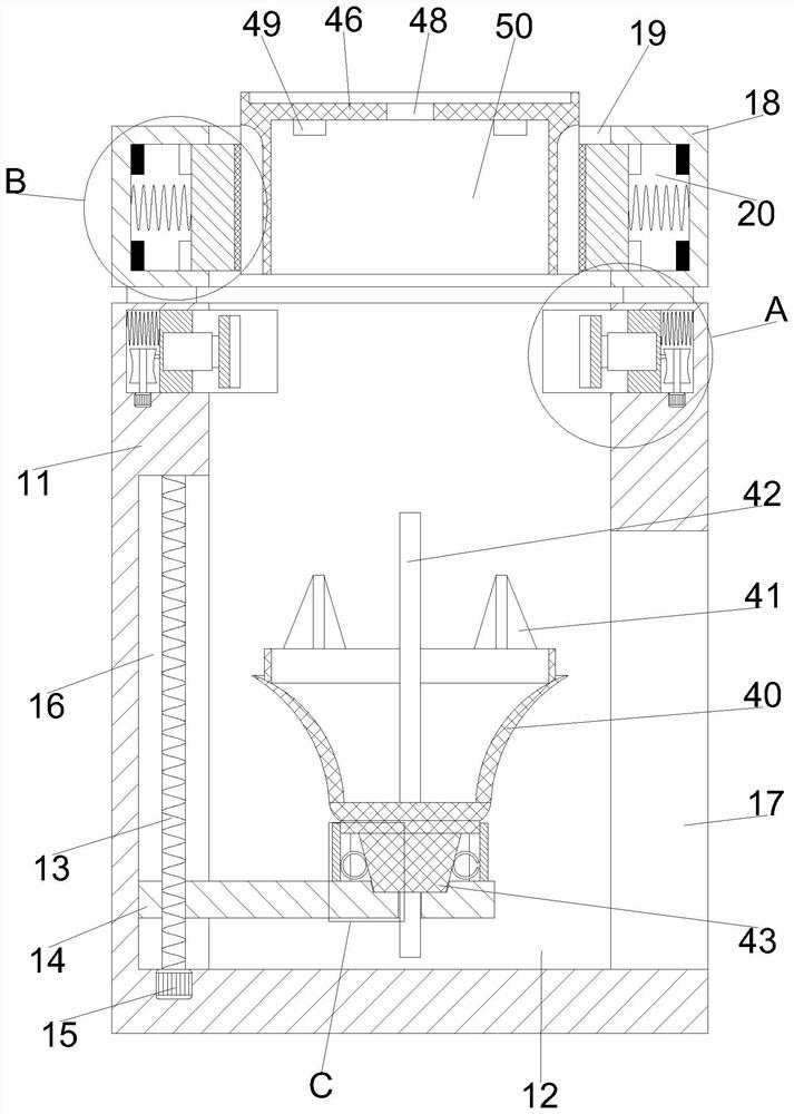
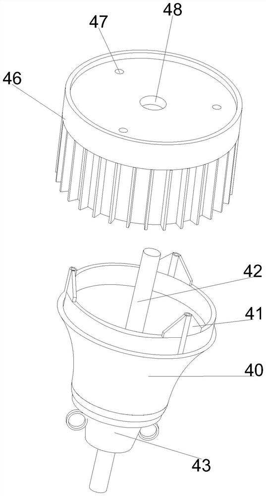
[0030] Specific embodiment one: please refer to Figure 1-7 An installation device for a combined lamp, comprising an assembly box 11, a placement plate 14, a clamping box 18, a main lamp body part, an auxiliary lamp body part and a correction part;

[0031] The clamping box 18 is fixed on the top of the assembly box 11, and the placement plate 14 slides up and down in the assembly box 11, and the placement plate 14 is used to support the auxiliary lamp body parts;

[0032] The main lamp body part is clamped in the clamping box 18, the top of the auxiliary lamp body part is fixed with elastic elements, and there are multiple elastic elements, and each elastic element is arranged in a circular array around the central axis of the auxiliary lamp body part. Each elastic element is the same, when the main lamp body part is connected with the auxiliary lamp body part, the elastic element extends into the main lamp body part, so that the main lamp body part and the auxiliary lamp bo...

specific Embodiment 2

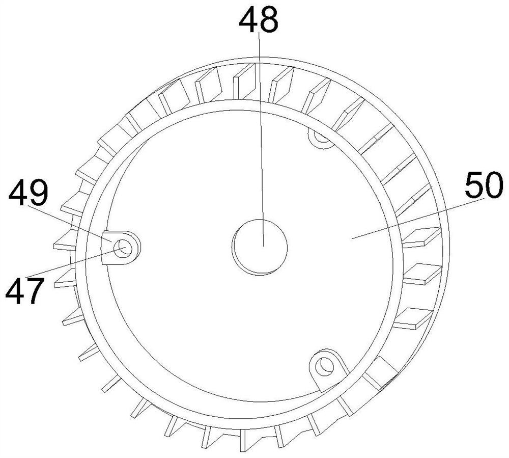
[0042] Specific embodiment 2: On the basis of specific embodiment 1, an installation device for a combined lamp, the lower lamp body 40 is put into the transport cavity 12 through the discharge cavity 17, and the base 43 is placed in the The cavity 44 fits the inner wall of the placement cavity 44, and at the same time, the stabilizing blocks 45 on both sides fit the outer circular surface of the base 43, and the upper lamp body 46 is put into the clamping cavity 19. The external power control device controls the electromagnets 21 on both sides to close, so that the electromagnets 21 on both sides lose their magnetism, so that the magnetic blocks 22 are no longer attracted, and the clamping plates 23 on both sides are pushed to slide toward each other by the thrust springs 25 on both sides. Thereby the both sides of upper lamp body 46 are clamped, and at this moment, through the cushioning of the cushions 24 on both sides, the clamping plate 23 will not pinch the upper lamp bod...


PUM


Abstract

The invention discloses installation equipment of a combined lamp, and belongs to the related field of lamps. Mounting equipment of a combined lamp comprises an assembling box, a placing plate, a clamping box, a main lamp body part, an auxiliary lamp body part and a correcting part. The clamping box is fixedly arranged at the top end of the assembling box, and the containing plate is arranged in the assembling box in an up-down sliding mode and used for bearing the auxiliary lamp body component. The main lamp body part is clamped in the clamping box, a plurality of elastic elements are fixedly arranged at the top end of the auxiliary lamp body part, the elastic elements are arranged in a circumferential array mode with the central axis of the auxiliary lamp body part as the center, all the elastic elements are the same, and when the main lamp body part is connected with the auxiliary lamp body part, the elastic elements stretch into the main lamp body part; therefore, the main lamp body part and the auxiliary lamp body part are fixedly connected through friction force. According to the scheme, the correcting component is arranged, the correcting component can push the combined lamp, and therefore the lamp can be combined and installed more conveniently and rapidly.

Description

technical field [0001] The invention belongs to the related field of lamps, and more specifically relates to a device for installing a combined lamp. Background technique [0002] Lamps are a general term for lighting tools, which are divided into chandeliers, table lamps, wall lamps, floor lamps, etc. Now there is a combined lamp on the market. The lamp does not need to be assembled with traditional threaded connections, but uses connection methods such as clamping and buckling, so that the lamp has stronger connection performance and effect. [0003] The assembly of some existing combined lamps is cumbersome, and some elastic parts need to be manually clamped, and even need to spend a lot of force to clamp, which consumes a lot of manpower and affects the production efficiency at the same time. Therefore, a kind of It can quickly and not rely on manual installation of lamps and lanterns to improve the installation efficiency of combined lamps. Contents of the invention ...

Claims


Application Information

Patent Timeline
Patent Type & Authority Applications(China)
IPC IPC(8): F21V17/10F21V17/16F21V17/12
CPCF21V17/10F21V17/16F21V17/12F21V17/105
Inventor 王建钟
Owner 绍兴上虞舜源照明电器有限公司
Learn More