Measurement and calibration device for aluminum product production and processing

A technology for calibrating devices and aluminum products, which is applied in the direction of measuring devices, mechanical measuring devices, and mechanical devices, etc. It can solve problems such as shaking of aluminum products, inability to turn over aluminum products, and unclear measurement results, so as to improve stability , save the time of angle and direction, and ensure the effect of stability

Pending Publication Date: 2022-04-29
杭州萧宏康美盛铝业有限公司
View PDF11 Cites 0 Cited by
  • Summary
  • Abstract
  • Description
  • Claims
  • Application Information

AI Technical Summary

Problems solved by technology

[0007] The object of the present invention is to provide a measuring and calibrating device for the production and processing of aluminum products, so as to solve the above-mentioned background technology that requires staff to constantly adjust the direction of aluminum products. The existing calibration device cannot turn over and shake the aluminum products. The frequency will drive the aluminum products to shake, and the measurement results are not clear enough

Method used


Image

  • Measurement and calibration device for aluminum product production and processing
  • Measurement and calibration device for aluminum product production and processing
  • Measurement and calibration device for aluminum product production and processing

Examples


Embodiment 1

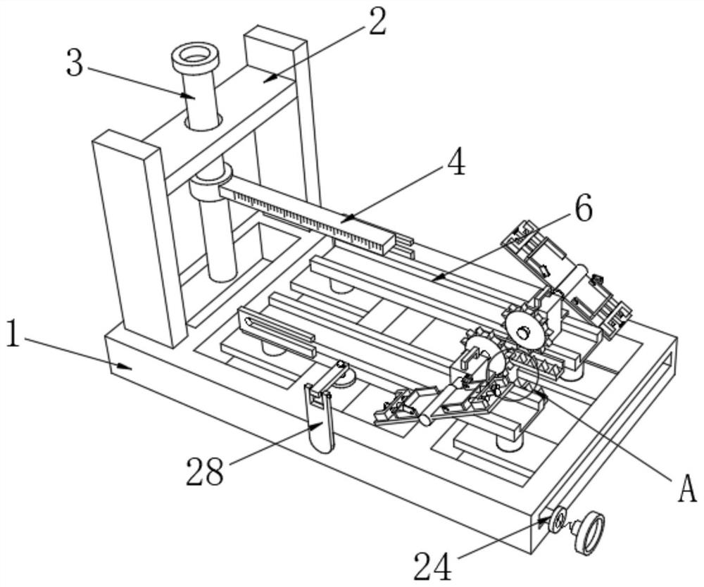
[0034] like Figure 1-7As shown, a measuring and calibrating device for the production and processing of aluminum products includes a calibrating device body 1, a support frame 2, a movable column 3, a measuring ruler 4, a buffer seat 5, a supporting plate 6, a limit frame 7, a slider 8, and a handle 9. Gear 10, rack 11, connecting column 12, connecting plate 13, fixed frame 14, telescopic column 15, buffer column 16, first spring 17, limit cover 18, first rotating shaft 19, auxiliary sleeve 20, restraint Belt 21, clamping block 22, card slot 23, connecting block 24, extension column 25, second spring 26, magnifying glass 27, auxiliary frame 28, second rotating shaft 29, moving sleeve 30 and lighting lamp 31, the top of calibration device body 1 One side of the support frame 2 is fixedly installed, the top of the support frame 2 is interspersed with a movable column 3, and one end of the movable column 3 is threaded with a measuring ruler 4, and the other side of the top of th...

Embodiment 2

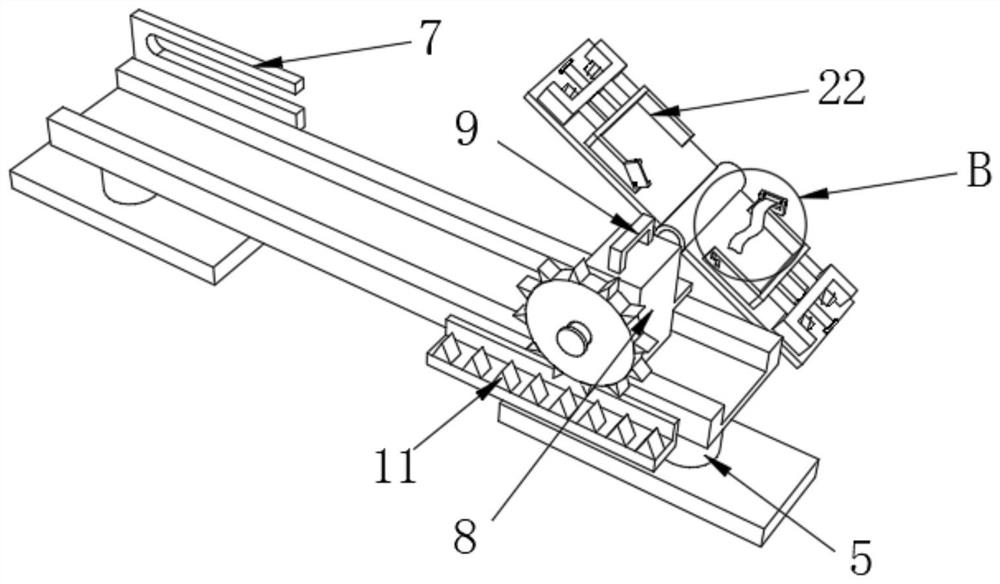
[0036] On the basis of Example 1, as figure 2 , image 3 and Figure 4 As shown, one side of the four fixed mounts 14 is rotatably connected with a telescopic column 15, the other side of the four fixed mounts 14 is interspersed with two buffer columns 16, and the outside of the eight buffer columns 16 is wound with a first Spring 17, one end of two adjacent buffer columns 16 is fixedly installed with clamping block 22, and one end of eight first springs 17 is respectively fixedly connected with one side of four fixed mounts 14, and the eight first springs 17 The other end is fixedly connected with the outer walls of the eight buffer columns 16 respectively. The present invention is provided with a limit cover 18, a first rotating shaft 19, a restraint belt 21, a draw-in groove 23, a telescopic column 15 and a clamping block 22. Since the telescopic column 15 It is rotatably connected with one side of the fixed frame 14, and when the telescopic column 15 is rotated, it will...

Embodiment 3

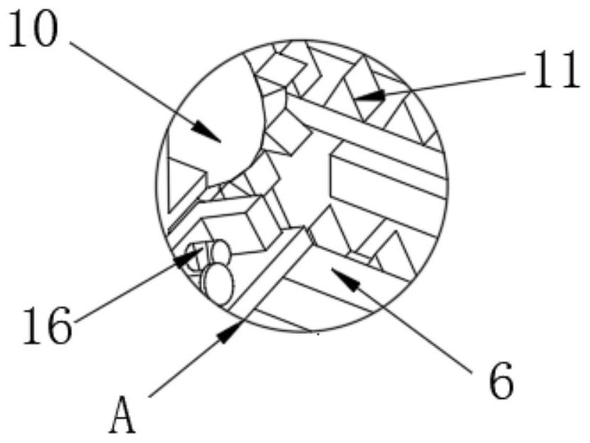
[0038] On the basis of embodiment one and embodiment two, such as figure 1 , Image 6 and Figure 7 As shown, one side of the four clamping blocks 22 is fixedly installed with a limit cover 18, and one side of the four limit covers 18 is interspersed with a first rotating shaft 19, and one end of the four first rotating shafts 19 is movable. Auxiliary sleeves 20 are provided, four auxiliary sleeves 20 are wound with restraint belts 21, one side of the four restraint belts 21 is fixedly equipped with two clamping blocks, and the other sides of the four clamping blocks 22 are all Two card slots 23 are provided, an extension column 25 is slidably installed on one side of the calibration device body 1, a connection block 24 is fixedly installed at one end of the extension column 25, and a second spring 26 is fixedly installed at the bottom end of the connection block 24. One end of the second spring 26 is fixedly equipped with a magnifying glass 27, and the front of the calibrat...


PUM


Abstract

The invention relates to the technical field of novel pipe shrinkage machines, in particular to a measurement and calibration device for aluminum product production and machining. Comprising a calibration device body, a supporting frame, a movable column, a measuring scale, a buffer seat, a supporting plate, a limiting frame, a sliding block, a handle, a gear, a rack, a connecting column, a connecting plate, a fixing frame, a telescopic column, a buffer column, a first spring, a limiting cover, a first rotating shaft, an auxiliary sleeve, a binding belt, a clamping block, a clamping groove, a connecting block, an extension column, a second spring, a magnifying lens, an auxiliary frame, a second rotating shaft, a movable sleeve and an illuminating lamp. By arranging the supporting plate, the limiting frame, the sliding block, the gear, the rack and the connecting column, the sliding block slides at the top end of the supporting plate, a handle is pulled, the sliding block can be moved to a proper position, the surface of an aluminum product can be comprehensively measured through the structure, and the time for workers to adjust the angle and direction of the aluminum product in the later period is saved.

Description

technical field [0001] The invention relates to the technical field of measuring and calibrating devices, in particular to a measuring and calibrating device for production and processing of aluminum products. Background technique [0002] Aluminum products are a general term for daily necessities and industrial products processed with aluminum alloy as the main raw material. Aluminum alloy is a general term for alloys based on aluminum. There are nickel, iron, titanium, chromium, lithium, etc. Aluminum alloy has low density, but relatively high strength, which is close to or exceeds high-quality steel. It has good plasticity and can be processed into various profiles. It has excellent electrical conductivity, thermal conductivity and corrosion resistance. Widely used in industry, the amount of use is second only to steel, aluminum is very soft, not strong, has good ductility, can be drawn into filaments and rolled into foil, and is widely used in the manufacture of wires, c...

Claims


Application Information

Patent Timeline
Patent Type & Authority Applications(China)
IPC IPC(8): G01B5/00
CPCG01B5/00
Inventor 高猛
Owner 杭州萧宏康美盛铝业有限公司
Why Eureka
Try Eureka