
Method and system for realizing online monitoring of carbon emission of coal-fired power generation unit and storage medium

A technology for generating sets and carbon emissions, applied in system integration technology, information technology support systems, computer-aided design, etc., can solve the problems of weak guidance on carbon reduction, lag in verification results, and large data errors.

Pending Publication Date: 2022-04-29
STATE GRID HUBEI ELECTRIC POWER RES INST +2
View PDF2 Cites 4 Cited by
  • Summary
  • Abstract
  • Description
  • Claims
  • Application Information

AI Technical Summary

Benefits of technology

The technical effects of this patented technology are that it allows companies within their own company or organization (PCA) to manage different types of fuel produced from multiple sources without relying on external resources like fossil fuels. This helps reduce greenhouse gas emissions while also improving efficiency.

Problems solved by technology

Technological Problem: Current measures used to monitor green house gases have limitations that make them difficult or impracticable at times when they require frequent updates due to delayed measurements caused by factors like temperature changes over time. Additionally, current systems only measure specific parts of the plant rather than comprehensively analyzed across all aspects of it.

Method used


Image

  • Method and system for realizing online monitoring of carbon emission of coal-fired power generation unit and storage medium
  • Method and system for realizing online monitoring of carbon emission of coal-fired power generation unit and storage medium
  • Method and system for realizing online monitoring of carbon emission of coal-fired power generation unit and storage medium

Examples


Embodiment Construction

[0034] The technical solutions in the embodiments of the present application will be described below with reference to the drawings in the embodiments of the present application. It should be noted that like numerals and letters denote similar items in the following figures, therefore, once an item is defined in one figure, it does not require further definition and explanation in subsequent figures.

[0035] The term "comprises", "comprises" or any other variation thereof is intended to cover a non-exclusive inclusion such that a process, method, article or apparatus comprising a set of elements includes not only those elements but also other elements not expressly listed elements, or also elements inherent in such a process, method, article, or apparatus. Without further limitations, an element defined by the phrase "comprising a ..." does not exclude the presence of additional identical elements in the process, method, article or apparatus comprising said element.

[0036]...


PUM


Abstract

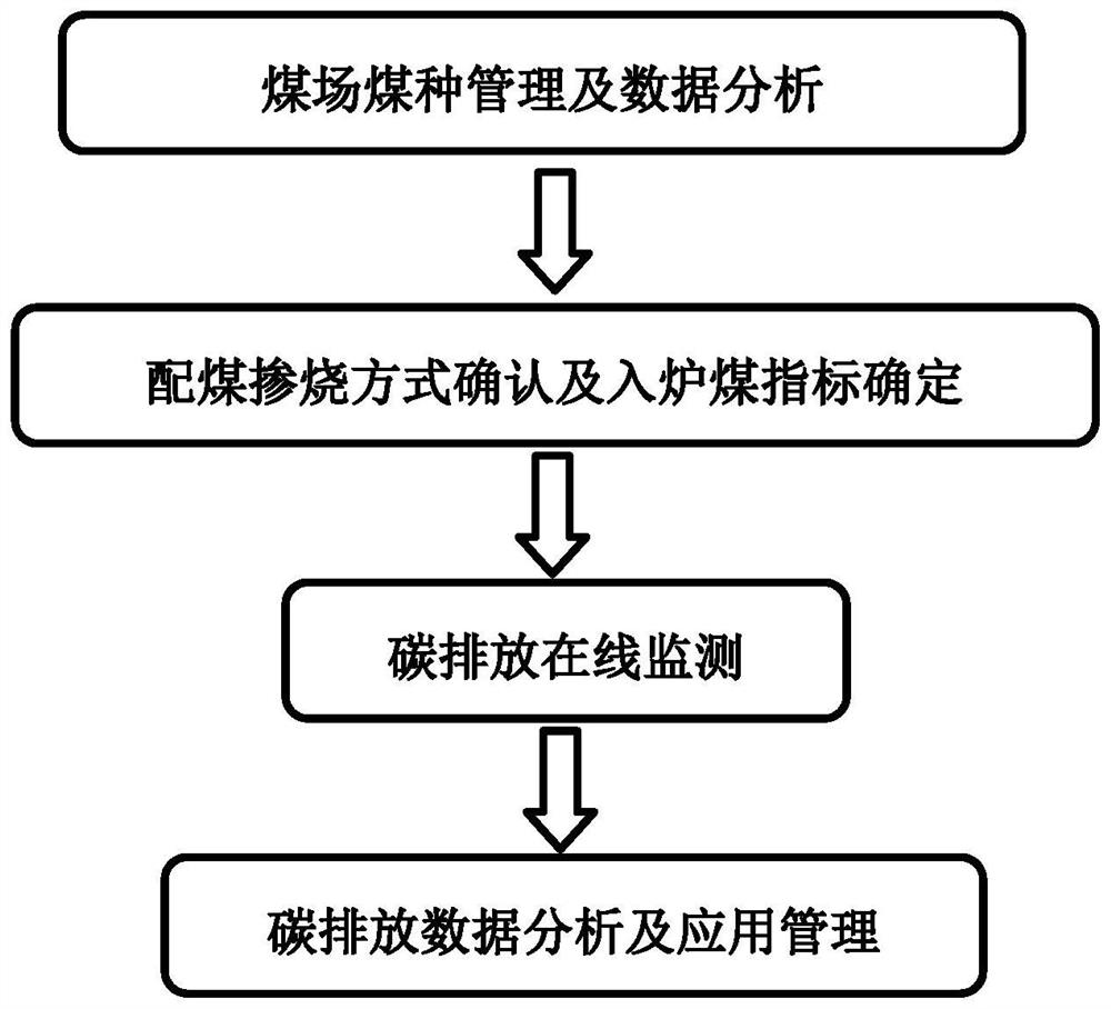
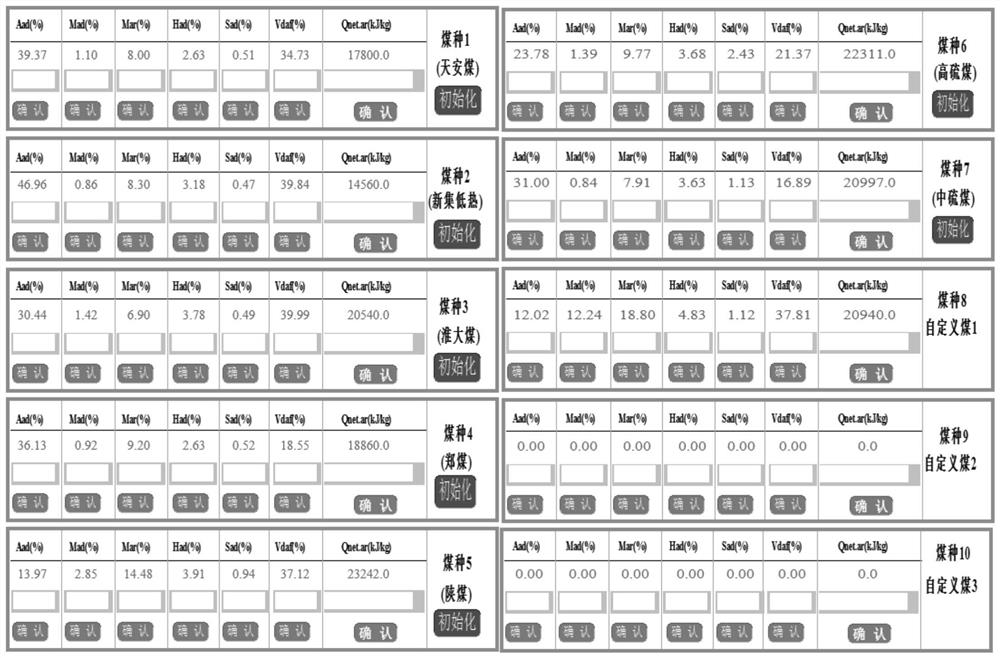
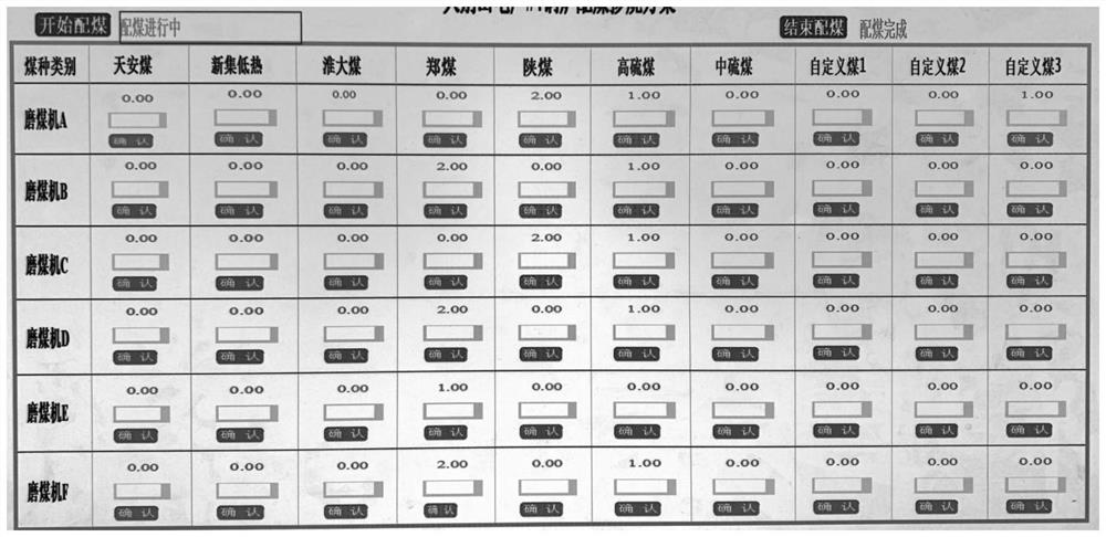
The invention provides a method and a system for realizing on-line monitoring of carbon emission of a coal-fired power generation unit and a storage medium. The method comprises the following specific steps: coal type management and data analysis of a coal yard; confirming a coal blending combustion mode and determining as-fired coal indexes; carbon emission on-line monitoring: establishing a carbon emission on-line monitoring calculation model, and respectively calculating the carbon emission generated by combustion of the power generation enterprise and the carbon emission generated by purchased power; and carbon emission data analysis and application management: establishing a carbon emission data analysis and application model, and completing unit carbon emission intensity benchmarking analysis, unit carbon reduction measure analysis and guidance, and unit carbon asset management. According to the invention, comprehensive and real-time perception of the carbon emission data of the power generation enterprise is achieved, and through establishment of the data analysis model, carbon reduction, carbon control and carbon transaction of the power generation enterprise are guided, and a power grid scheduling department is guided to make a low-carbon scheduling strategy.

Description


Claims


Application Information

Patent Timeline
Owner STATE GRID HUBEI ELECTRIC POWER RES INST
Learn More