Intelligent micro circuit breaker power supply module circuit compatible with multiple rated working voltages
A voltage-compatible, power module technology, applied in overcurrent protection, cooling/ventilation/heating transformation, casing/cabinet/drawer components, etc., can solve the problem of inability to connect and install, endangering circuit safety , The current surge can not cut off the power quickly, etc., to improve the strength of the connection and the effect of improving the wiring efficiency
- Summary
- Abstract
- Description
- Claims
- Application Information
AI Technical Summary
Problems solved by technology
Method used
Image
Examples
Embodiment 1
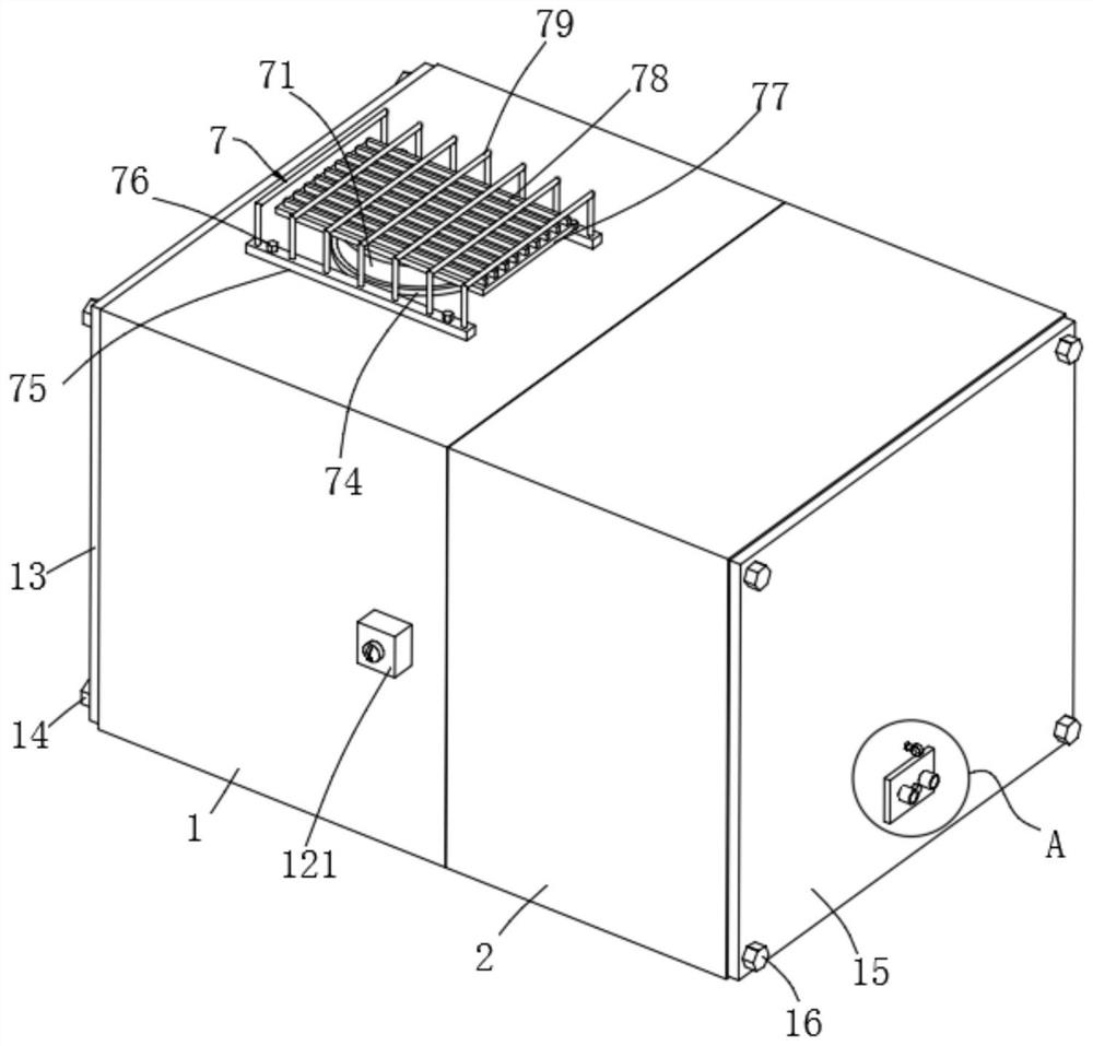
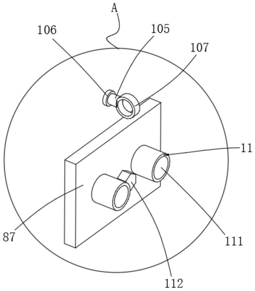
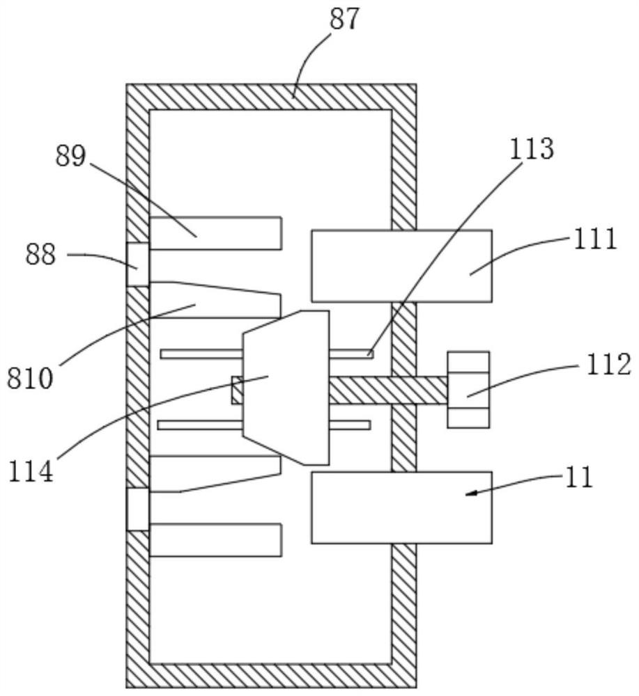
[0054] Example 1, please refer to Figure 1-11 , a smart micro-cutoff power supply module circuit compatible with multiple rated working voltages, including:
[0055] The left half shell 1, the left end opening is fixedly connected with the left end plate 13 through the left bolt 14, the right end of the left half shell 1 is connected to the left end of the right half shell 2 through the half shell connecting unit 12, and the right end of the right half shell 2 is connected through the right bolt 16 Right end plate 15;
[0056] The input cable compression execution unit 3 includes a support 31, a conductive seat 32, a compression block 33, a swing rod 34, a movable rod 35, an incoming line insulation cylinder 36, an incoming line guide cylinder 37, a push-pull rod 38, and the left half The inner bottom of the shell 1 is fixedly connected with two conductive seats 32 through the support 31, the left end of each conductive seat 32 is movably connected with the bottom end of the...
Embodiment 2
[0080] Example 2, please refer to figure 1 , 4 And 6, a smart micro-cutoff power supply module circuit compatible with multiple rated working voltages, this embodiment is a further description of Embodiment 1:
[0081] The half-shell connection unit 12 includes a hollow block 121, a pull block 122, a pull-out ring 123, a spring 124, a fixed stop ring 125, a post 126, a post 127 and an inner sleeve 128, and the inner side of the left end of the right half shell 2 is fixedly connected An inner sleeve 128 is arranged, and the left end of the inner sleeve 128 is socketed on the inside of the right end of the left half-shell 1, and the front and rear sides of the left end of the right half-shell 2 are respectively fixedly connected with inserting posts 126, and the inserting posts 126 are connected with the inserting posts on the right side of the left half-shell 1. The front side of the left half-shell 1 is fixed with the installation hollow block 121 corresponding to the inserti...
Embodiment 3
[0083] Example three, please refer to figure 1 , 8 and 10, a smart micro-cutoff power supply module circuit compatible with multiple rated operating voltages, the structure of this embodiment is roughly the same as that of Embodiment 2, the difference lies in:
[0084] A heat dissipation unit 7 is also included, the bottom of the heat dissipation unit 7 is connected to the circuit board 6 , and the top of the heat dissipation unit 7 extends to the upper side of the top of the left half shell 1 . The heat dissipation unit 7 can conduct and dissipate the heat accumulated on the circuit board 6 to the outside of the left half-shell 1 to improve the safety of use.
[0085] The heat dissipation unit 7 includes a heat conduction column 71, a silicone grease 72, a heat pipe 73, a slip ring 74, a fixing bar 75, a bolt 76, a heat dissipation plate 77, a heat dissipation fin 78 and a protective arched column 79, and the top mounting hole of the left half shell 1 A slip ring 74 is inla...
PUM
 Abstract
Description
Claims
Application Information
 - R&D
- Intellectual Property
- Life Sciences
- Materials
- Tech Scout
- Unparalleled Data Quality
- Higher Quality Content
- 60% Fewer Hallucinations
Browse by: Latest US Patents, China's latest patents, Technical Efficacy Thesaurus, Application Domain, Technology Topic, Popular Technical Reports.
© 2025 PatSnap. All rights reserved.Legal|Privacy policy|Modern Slavery Act Transparency Statement|Sitemap|About US| Contact US: help@patsnap.com


