
Flexibly designable converter cell

A converter and control unit technology, applied in the direction of output power conversion device, irreversible AC power input conversion to DC power output, electrical components, etc., can solve the problems of high logistics and storage costs, increased production costs, etc.

Pending Publication Date: 2022-04-29
SIEMENS AG
View PDF0 Cites 0 Cited by
  • Summary
  • Abstract
  • Description
  • Claims
  • Application Information

AI Technical Summary

Problems solved by technology

In addition, the large variety leads to increased production costs
Logistics and storage costs are also high

Method used


Image

  • Flexibly designable converter cell
  • Flexibly designable converter cell
  • Flexibly designable converter cell

Examples


Embodiment Construction

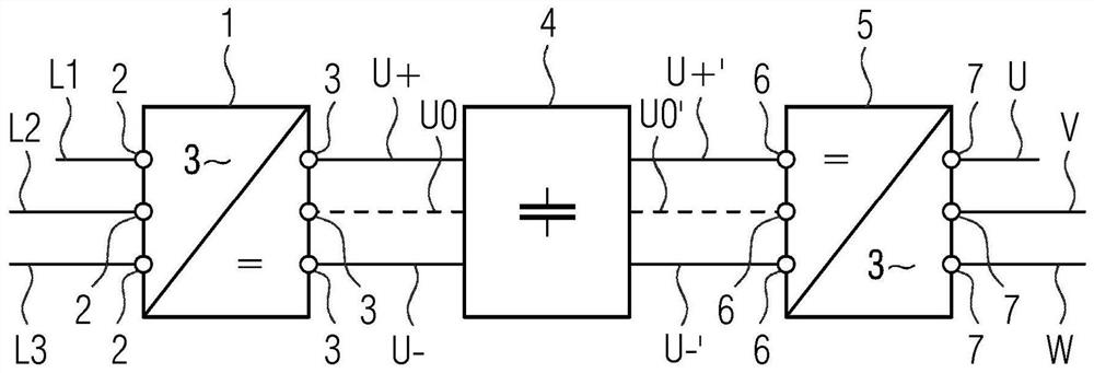
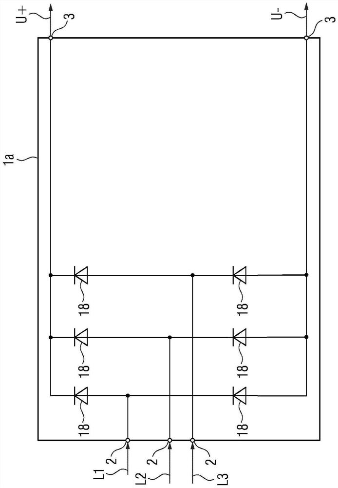
[0040] according to figure 1 , the converter unit firstly has a rectifier unit 1 as the basic functional unit. The AC voltages L1 , L2 , L3 (phases), typically the three AC voltages of a three-phase grid, are fed to the rectifier unit 1 via the first power connection 2 of the rectifier unit 1 . The rectifier unit 1 is able to convert the AC voltage fed to it into at least two DC voltage potentials U+, U−. The rectifier unit 1 outputs DC voltage potentials U+, U− via the second power connection 3 . Possible designs of the rectifier unit 1 will be explained in more detail later.

[0041] The output DC voltage potentials U+, U− are fed to the DC voltage connection 4 . The DC voltage connection 4 is another main functional unit of the converter unit. The DC voltage connection device 4 usually has a capacitor network internally in order to smooth the DC voltage potentials U+, U−.

[0042] The direct voltage potentials U+, U− are fed to the inverter unit 5 . The inverter unit ...


PUM


Abstract

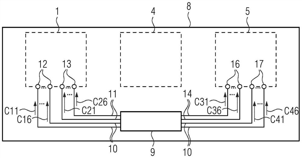
A converter unit has a main printed circuit board (8) on which at least one functional module (1, 5) is arranged. By means of the functional module (1, 5), at least one alternating voltage (L1, L2, L3, U, V, W) fed to the functional module (1, 5) via a first power supply interface (2, 7) of the functional module (1, 5) can be converted into at least two direct-current piezoelectric potentials (U +, U-, U0) output via a second power supply interface (3, 6) of the functional module (1, 5). The main printed circuit board (8) has conductor tracks (10, 11, 14, 15) via which the control signals (C11 to C46) can be fed to the control interfaces (12, 13, 16, 17). The main printed circuit board (8) has conductor tracks (10, 11, 14, 15) extending from the control unit (9) to the first and second control interfaces (12, 13, 16, 17) of the main printed circuit board (8), and the first and second control signals (C11 to C46) can be fed to the first and second control interfaces (12, 13, 16, 17) via the conductor tracks. The functional module (1, 5) is at least mechanically connected to the main printed circuit board (8) at least in the region of the first and second control interfaces (12, 13, 16, 17). However, the functional module is designed in such a way that it does not use the first control signal (C11 to C16, C31 to C36) and / or the second control signal (C21 to C26, C41 to C46).

Description

technical field [0001] The invention relates to a converter unit, [0002] - wherein the converter unit has a main printed circuit board, [0003] - wherein at least one functional module is arranged on the main printed circuit board, [0004] - wherein, by means of the functional module, at least one alternating voltage fed to the functional module via a first power supply connection of the functional module can be converted into at least two direct voltage potentials output via a second power supply connection of the functional module, [0005] - wherein the main printed circuit board has conductor tracks via which the first and second control signals can be fed to the first and second control interfaces of the main printed circuit board, [0006] - wherein the functional module is at least mechanically connected to the main printed circuit board at least in the region of the first and second control interface. [0007] The invention also relates to the combination of two...

Claims


Application Information

Patent Timeline
IPC IPC(8): H02M5/458H02M7/04H02M7/537H02M1/088H02M1/44
CPCH02M5/458H02M7/04H02M7/537H02M1/088H02M1/44H05K7/14322H05K7/1432
Inventor 卡劳斯·尼贝尔莱因法尔科·鲍曼勒内·容海内尔珍妮弗·劳特纳马蒂亚斯·奈里格延斯·施门格
Owner SIEMENS AG
Learn More