
Gravity type fiber grating tilt angle sensor

An inclination sensor, fiber grating technology, applied in instruments, measuring inclination, using optical devices, etc., can solve problems such as inability to function, detection failure, etc., to achieve the effect of reducing friction, stable structure, and easy installation

Inactive Publication Date: 2022-05-03
WUHAN CITY VOCATIONAL COLLEGE
View PDF1 Cites 1 Cited by
  • Summary
  • Abstract
  • Description
  • Claims
  • Application Information

AI Technical Summary

Problems solved by technology

[0003] Patent CN212340236U describes a gravity fiber grating inclination sensor. The fiber grating inclination sensor is vertically fixed on the beam, and the wavelength of the fiber grating does not change. When the fiber grating inclination sensor tilts, the gravity component of the copper ball will change. The pulling force of the fiber grating on the copper ball will change. The parts of the fiber grating inclination sensor can be disassembled at any time, and can be reassembled after disassembly, but the inner ball will directly act on the fiber tube, and the pressure on the inner fiber may be Is there a consequence that cannot be applied to itself, causing the detection to fail?

Method used


Image

  • Gravity type fiber grating tilt angle sensor
  • Gravity type fiber grating tilt angle sensor
  • Gravity type fiber grating tilt angle sensor

Examples


Embodiment Construction

[0035] The following will clearly and completely describe the technical solutions in the embodiments of the present invention with reference to the accompanying drawings in the embodiments of the present invention. Obviously, the described embodiments are only some, not all, embodiments of the present invention. Based on the embodiments of the present invention, all other embodiments obtained by persons of ordinary skill in the art without making creative efforts belong to the protection scope of the present invention.

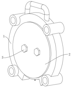
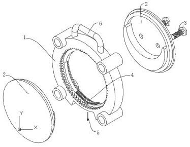
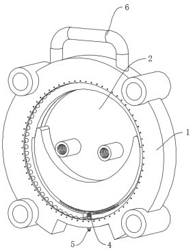
[0036] see Figure 1-Figure 9, the present invention provides a technical solution: a gravitational fiber grating inclination sensor, including a ring-shaped main body 1, the inner wall of the main body 1 is rotatably connected with a vertical block 2 with a low center of gravity, and the interior of the vertical block 2 is set There are two connecting screws 3 to keep it stable. A hollow load-bearing mechanism 4 is provided at the bottom of the inner wall of ...


PUM


Abstract

The invention discloses a gravity type fiber bragg grating tilt angle sensor, which comprises a circular ring-shaped main body, the inner wall of the main body is rotatably connected with a vertical block with a low gravity center, two connecting screws for keeping the vertical block stable are arranged in the vertical block, a hollow bearing mechanism is arranged at the bottom of the inner wall of the main body, and the hollow bearing mechanism is connected with the vertical block. An optical fiber tube is arranged at the hollow position of the bearing mechanism, the interior of the optical fiber tube is connected with an optical fiber, and the optical fiber makes contact with the outer wall of the plumb block. The main body is installed on a measured beam column, after the beam column inclines, the main body inclines along with the inclination of the beam column, the center of the vertical block is low, so that the angle between the vertical block and the ground is kept unchanged, and the optical fiber tube which is originally collinear with the axis of the vertical block forms an angle with the axis. Therefore, the component force of the plumb block on the optical fiber in the optical fiber tube is changed, and the wavelength change of the optical fiber can be measured through the change of the component force, thereby measuring the changed angle of the beam column.

Description

technical field [0001] The invention belongs to the technical field of optical fiber grating inclination sensors, in particular to a gravity type optical fiber grating inclination sensor. Background technique [0002] Uneven settlement is the main factor that causes the structure to tilt, and the gravity fiber grating inclination sensor is the main means to monitor the tilt of the building. A gravitational fiber grating inclination sensor was developed by using the gravitational principle, and the quantitative relationship formula between the wavelength difference and inclination angle of the fiber grating was established to realize the long-term monitoring of the fiber grating sensor. [0003] Patent CN212340236U describes a gravity fiber grating inclination sensor. The fiber grating inclination sensor is vertically fixed on the beam, and the wavelength of the fiber grating does not change. When the fiber grating inclination sensor tilts, the gravity component of the copper...

Claims


Application Information

Patent Timeline
Patent Type & Authority Applications(China)
IPC IPC(8): G01C9/00G01C9/02G01B11/26
CPCG01C9/00G01C9/02G01B11/26
Inventor 袁博袁银权
Owner WUHAN CITY VOCATIONAL COLLEGE
Learn More