Vehicle thermal management system and vehicle

A thermal management system and vehicle technology, applied in the field of vehicle thermal management systems, can solve the problems of poor air conditioning heating capacity, increased cost, energy waste, etc., to increase the suction temperature and suction pressure, avoid energy waste, and improve heating effect of ability

Pending Publication Date: 2022-05-06
MIND ELECTRONICS APPLIANCE CO LTD
View PDF0 Cites 1 Cited by
  • Summary
  • Abstract
  • Description
  • Claims
  • Application Information

AI Technical Summary

Problems solved by technology

For the thermal management system of the air conditioner, when the ambient temperature is low, the heating capacity of the air conditioner is poor, and it is usually difficult to meet the heating demand of the passenger compartment; for the thermal management system of the motor, the motor will generate heat when driving the vehicle. In order to ensure the normal operation of the motor, it is necessary to dissipate heat and cool the motor; for the battery thermal management system, in order to ensure that the battery pack can work within its suitable temperature range, it is necessary to cool the battery pack with too high temperature, and to low battery pack for heating
[0003] Since the existing air-conditioning thermal management system, motor thermal management system, and battery thermal management system operate independently of each other, on the one hand, the heat collection planning of the vehicle thermal management system will be unreasonable, resulting in energy waste, and on the other hand, it will lead to The number of pipelines, valves, joints and other components in the vehicle thermal management system increases, resulting in an increase in cost

Method used


Image

  • Vehicle thermal management system and vehicle
  • Vehicle thermal management system and vehicle
  • Vehicle thermal management system and vehicle

Examples


Embodiment Construction

[0036] Specific embodiments of the present disclosure will be described in detail below in conjunction with the accompanying drawings. It should be understood that the specific embodiments described here are only used to illustrate and explain the present disclosure, and are not intended to limit the present disclosure.

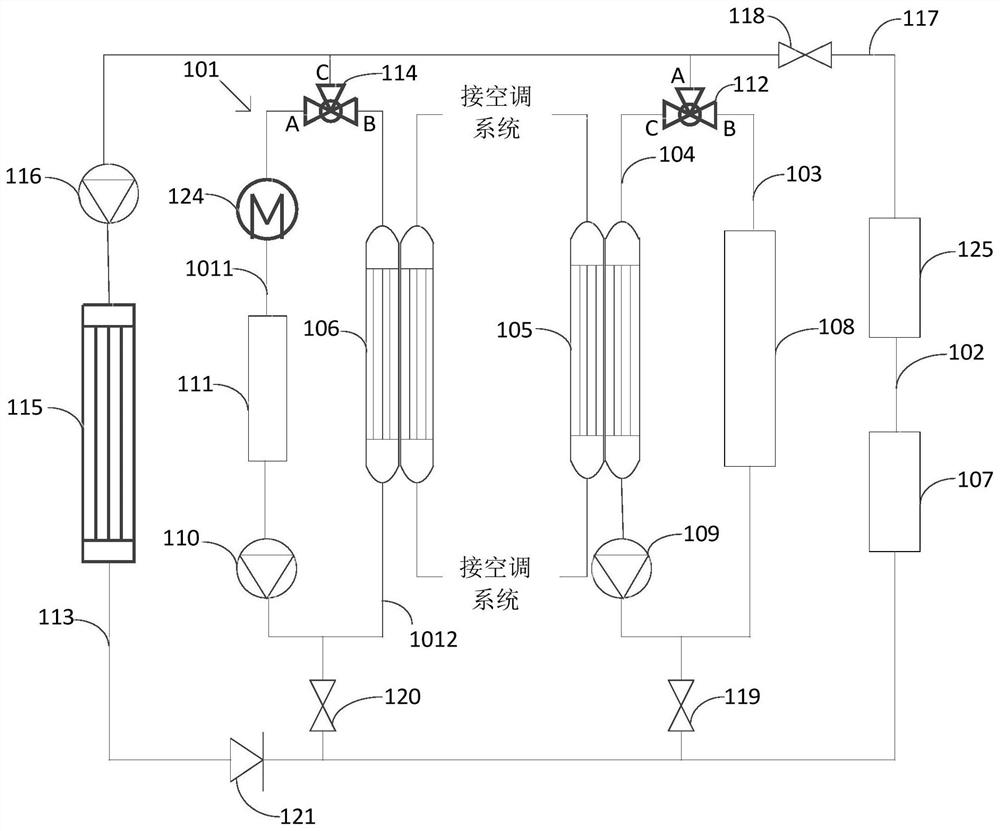
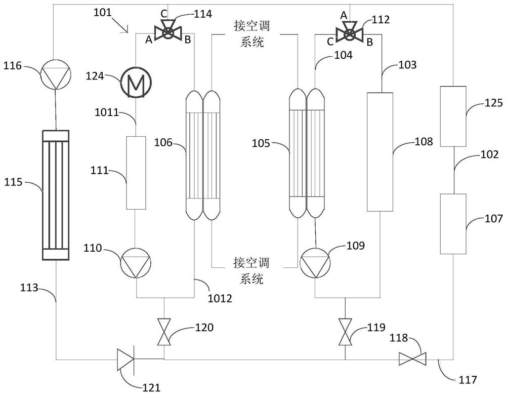
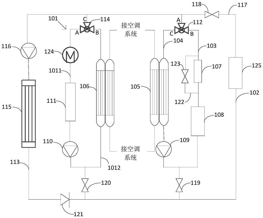
[0037] like Figure 1 to Figure 10As shown, the present disclosure provides a vehicle thermal management system, including a coolant circuit 101, a first coolant flow path 102, a second coolant flow path 103, a third coolant flow path 104, a first heat exchanger 105 and The second heat exchanger 106 . Wherein, the first end of the first cooling liquid flow path 102, the first end of the second cooling liquid flow path 103, and the first end of the third cooling liquid flow path 104 are connected to each other, and the second end of the third cooling liquid flow path 104 The end is selectively connected with the second end of the first cooling liquid flow pa...


PUM


Abstract

The invention relates to a vehicle thermal management system and a vehicle. The system comprises a cooling liquid loop, a first cooling liquid flow path, a second cooling liquid flow path, a third cooling liquid flow path, a first heat exchanger and a second heat exchanger. The first end of the first cooling liquid flow path, the first end of the second cooling liquid flow path and the first end of the third cooling liquid flow path are connected with one another, and the second end of the third cooling liquid flow path is selectively connected with the second end of the first cooling liquid flow path or the second end of the second cooling liquid flow path; a motor is arranged on the first cooling liquid flow path or the second cooling liquid flow path, a battery pack is arranged on the second cooling liquid flow path, a first water pump is arranged on the third cooling liquid flow path, and the first heat exchanger is arranged in the third cooling liquid flow path and an air conditioning system of a vehicle heat management system at the same time. The second heat exchanger is arranged in the cooling liquid loop and the air conditioning system at the same time, and a second water pump and a warm air core body are further arranged on the cooling liquid loop.

Description

technical field [0001] The present disclosure relates to the technical field of vehicle thermal management systems, in particular, to a vehicle thermal management system and a vehicle. Background technique [0002] In the vehicle thermal management system, it usually includes the air-conditioning thermal management system, the motor thermal management system, and the battery thermal management system. For the thermal management system of the air conditioner, when the ambient temperature is low, the heating capacity of the air conditioner is poor, and it is usually difficult to meet the heating demand of the passenger compartment; for the thermal management system of the motor, the motor will generate heat when driving the vehicle. In order to ensure the normal operation of the motor, it is necessary to dissipate heat and cool the motor; for the battery thermal management system, in order to ensure that the battery pack can work within its suitable temperature range, it is ne...

Claims


Application Information

Patent Timeline
Patent Type & Authority Applications(China)
IPC IPC(8): B60H1/00B60H1/06B60K1/00B60K11/04B60L58/26B60L58/27H01M10/663H01M10/613H01M10/615H01M10/625
CPCB60H1/00342B60H1/06B60K1/00B60K11/04B60L58/26B60L58/27H01M10/663H01M10/613H01M10/615H01M10/625B60K2001/005B60K2001/006B60K2001/008H01M10/66B60L2240/34B60L2240/36B60L1/02B60L1/003B60H1/32284B60H1/00278B60H2001/00307B60H1/00885B60H1/00392B60K2001/003B60K11/02H01M10/6568
Inventor 尤古塔纳·贝努利
Owner MIND ELECTRONICS APPLIANCE CO LTD
Why Eureka
Try Eureka