Special small coal bunker suitable for deep peak regulation of 600MW unit

A small coal bunker, deep technology, used in packaging, loading/unloading, large containers, etc., can solve the problem of difficulty in switching between different coal types, and achieve the effect of rapid switching

Pending Publication Date: 2022-05-06
SHANGAN POWER PLANT OF HUANENG INT POWER CO LTD
View PDF16 Cites 0 Cited by
  • Summary
  • Abstract
  • Description
  • Claims
  • Application Information

AI Technical Summary

Problems solved by technology

[0006] The technical problem to be solved by the present invention is to provide a special small coal bunker suitable for deep peak regulation of 600MW units to solve the problem of difficulty in switching between different coal types due to the existing space and cost

Method used


Image

  • Special small coal bunker suitable for deep peak regulation of 600MW unit
  • Special small coal bunker suitable for deep peak regulation of 600MW unit
  • Special small coal bunker suitable for deep peak regulation of 600MW unit

Examples


Embodiment 1

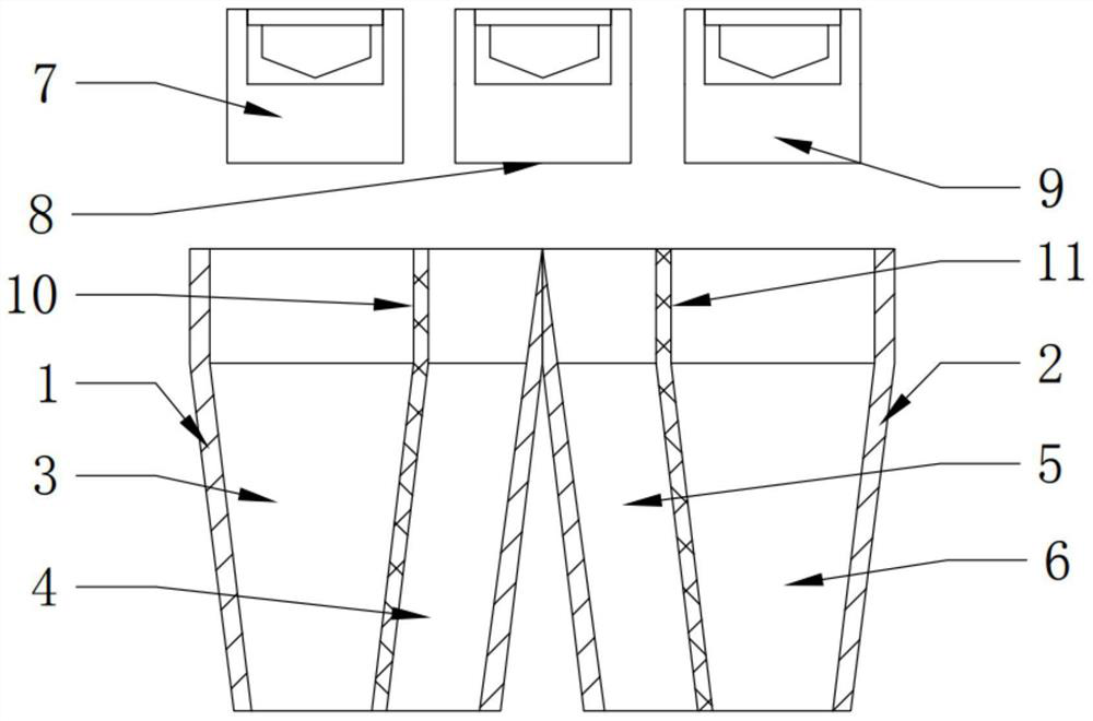
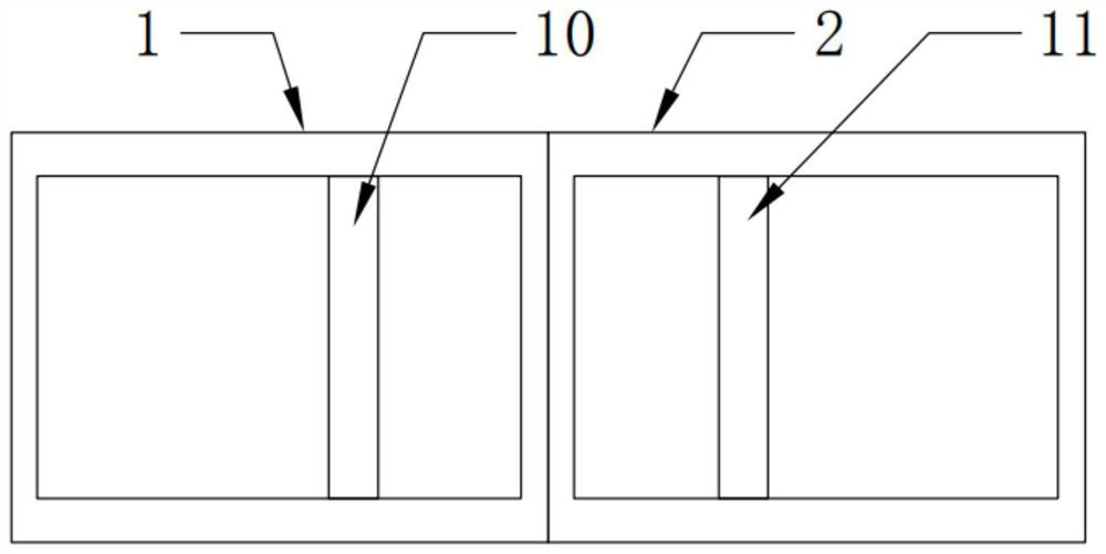
[0036] Such as figure 1 and figure 2 As shown, a special small coal bunker suitable for deep peak regulation of 600MW units includes two first coal bunkers 1 and second coal bunkers 2 arranged side by side. The first coal bunker 1 is provided with a first coal channel 3 and a The second coalway 4, the third coalway 5 and the fourth coalway 6 are arranged in the second coal bunker 2, the first coal plow 7 is arranged above the first coalway 3, the second coalway 4 and the third coalway A second coal plow 8 is arranged above the road 5, a third coal plow 9 is arranged above the fourth coal passage 6, and the first coal plow 7, the second coal plow 8 and the third coal plow 9 are arranged side by side;

[0037] A first dividing plate 10 is vertically arranged between the first coalway 3 and the second coalway 4, a second dividing plate 11 is vertically arranged between the third coalway 5 and the fourth coalway 6, and the first dividing plate 10 is adapted to the inner wall of...

Embodiment 2

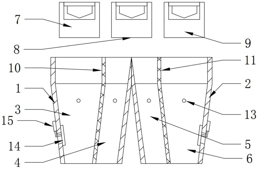
[0043] Such as image 3 and Figure 4 As shown, the structure of this embodiment is roughly the same as that of Embodiment 1, and this embodiment is further optimized on the basis of Embodiment 1: the first coalway 3, the second coalway 4, the third coalway 5 and the fourth coalway All are provided with breaking up stick 13 in 6, and breaking up stick 13 horizontal settings, the quantity of breaking up stick 13 is more than one.

[0044] Specifically, due to the humidity of the environment or other reasons, loose coal or coal powder condenses into agglomerates, in order to prevent the agglomerated falling coal from blocking the outlet, the first coal channel 3, the second coal channel 4, and the third coal channel 5 and the fourth coalway 6 are fixedly connected with a breaking stick 13, and the breaking stick 13 is fixed perpendicular to the inner walls of the first coalway 3, the second coalway 4, the third coalway 5 and the fourth coalway 6, The number of loose sticks 13 ...

Embodiment 3

[0048] Such as Figure 5 As shown, the structure of this embodiment is roughly the same as that of Embodiment 2, and this embodiment is further optimized on the basis of Embodiment 2: the upper ends of the opposite side of the second coalway 4 and the third coalway 5 are fixedly connected and provided with a buffer Article 16.

[0049] Specifically, in order to prevent the coal falling from the second coal plow 8 from colliding with the upper ends of the second coal passage 4 and the upper ends of the third coal passage 5 from colliding and splashing, the upper end of the side of the second coal passage 4 and the third coal passage 5 is fixed Connected together and bonded with a buffer strip 16, the buffer strip 16 is a rubber strip, on the one hand, the setting of the buffer strip 16 can abut and buffer the falling coal to prevent the falling coal from splashing around, and on the other hand, the buffer strip 16 can prevent Coal accumulation at the upper end of the side wher...


PUM


Abstract

The special small coal bunker comprises a first coal bunker body and a second coal bunker body which are arranged side by side, a first coal way and a second coal way are arranged in the first coal bunker body, a third coal way and a fourth coal way are arranged in the second coal bunker body, a first coal plough is arranged above the first coal way, and a second coal plough is arranged above the second coal way. A second coal plough is arranged above the second coal channel and the third coal channel, a third coal plough is arranged above the fourth coal channel, and the first coal plough, the second coal plough and the third coal plough are arranged in parallel. The first coal bunker and the second coal bunker are partitioned, the first coal plough, the second coal plough and the third coal plough are improved corresponding to the first coal bunker and the second coal bunker, and on the premise of limited space and cost, the two coal bunkers are added at the cost of minimum modification, so that special coal and daily coal are respectively coaled and do not interfere with each other, and the efficiency of coal loading is improved. Switching between the deep adjustment special coal and the common coal can be achieved, and the problem that under the condition of limited space and cost, coal type switching is difficult is effectively solved.

Description

technical field [0001] The invention belongs to the field of thermal power generation equipment, in particular to a special small coal bunker suitable for deep peak regulation of a 600MW unit. Background technique [0002] With the increasing frequency and depth of peak shaving in the power grid and the randomness of deep peak shaving, the existing coal blending method is passively delayed, and it often occurs that the dispatcher issues an order for deep peak shaving and then urgently adjusts the coal type. It has not met the scheduling requirements, seriously affecting the utilization hours of the units. Since the raw coal in the coal bunker is consumed, the special coal can only be adjusted in depth, so fast conversion cannot be realized. However, due to space and cost reasons, if the overall rectification is carried out, the problem of insufficient space and high cost will result, and the enterprise cannot afford it. [0003] With limited space and cost, it is imminent t...

Claims


Application Information

Patent Timeline
Patent Type & Authority Applications(China)
IPC IPC(8): B65D88/64B65D88/26B65G69/00
CPCB65D88/64B65D88/26B65G69/00
Inventor 张晓博李小龙马建坤刘小旺
Owner SHANGAN POWER PLANT OF HUANENG INT POWER CO LTD
Why Eureka
Try Eureka