Novel mica tape winding device

A technology of winding device and mica tape, which is applied in the direction of winding strips, transportation and packaging, thin material processing, etc. The effect of easy adjustment

Inactive Publication Date: 2022-05-06
HUAIHUA YONGGU ENERGY SAVING WALL MATERIAL
View PDF9 Cites 0 Cited by
  • Summary
  • Abstract
  • Description
  • Claims
  • Application Information

AI Technical Summary

Problems solved by technology

[0004] The purpose of the present invention is to provide a novel mica tape winding device to solve the problem that the existing automatic tape winding machine proposed in the above-mentioned background technology will arrange the motor and the winding reel on the front and rear surfaces of the substrate respectively during use. Moreover, the height of the winding reel can be changed by adjusting the height of the base plate. However, since multiple bolts need to be disassembled and assembled each time the height of the base plate is adjusted, the height adjustment method of the base plate is relatively cumbersome and not simple enough. Disadvantages

Method used


Image

  • Novel mica tape winding device
  • Novel mica tape winding device
  • Novel mica tape winding device

Examples


Embodiment 1

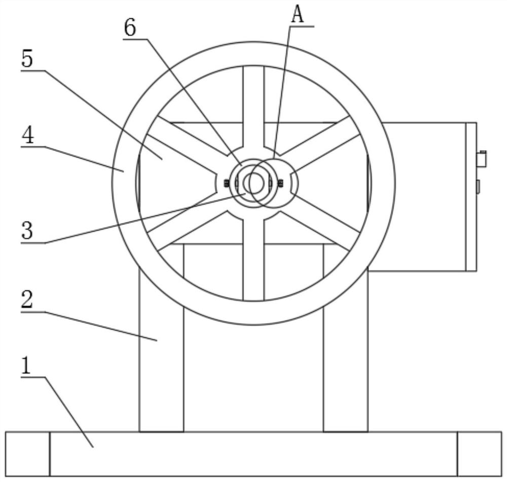
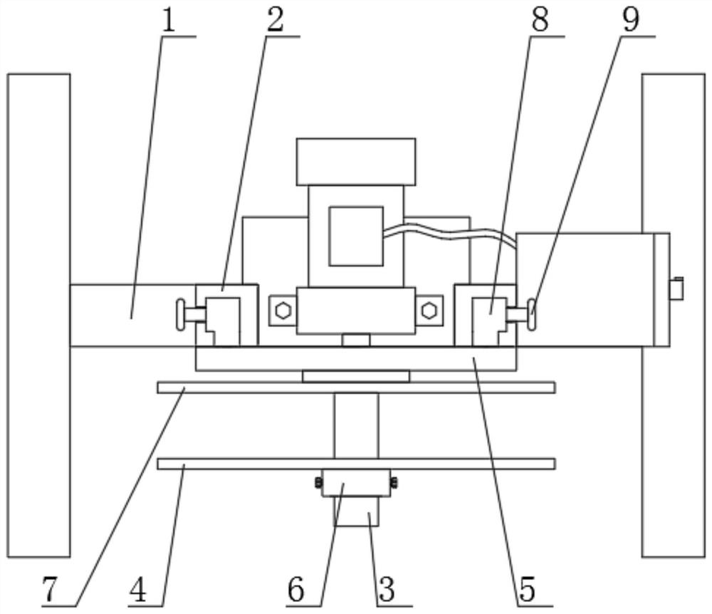
[0023] see Figure 1 to Figure 3 , the present invention provides a technical solution: a novel mica tape winding device, comprising a frame 1 and a substrate 5 arranged on the top of the frame 1, and the front surface of the substrate 5 is provided with a rotating shaft 3, and the surface of the rotating shaft 3 is provided with The inner baffle 7 and the outer baffle 4, the inner baffle 7 is fixedly connected with the rotating shaft 3, the outer baffle 4 is directly sleeved on the surface of the rotating shaft 3, the inner baffle 7 and the outer baffle 4 form a winding reel assembly, and the frame The top of 1 is symmetrically fixed with two struts 2 by bolts, the rear surface of the base plate 5 is symmetrically provided with two L-shaped sliders 8 by welding, and the interior of the struts 2 is provided with a matching L-shaped slider 8. L-shaped chute, the L-shaped slider 8 is inside the L-shaped chute, so that the L-shaped slider 8 can slide inside the L-shaped chute, th...

Embodiment 2

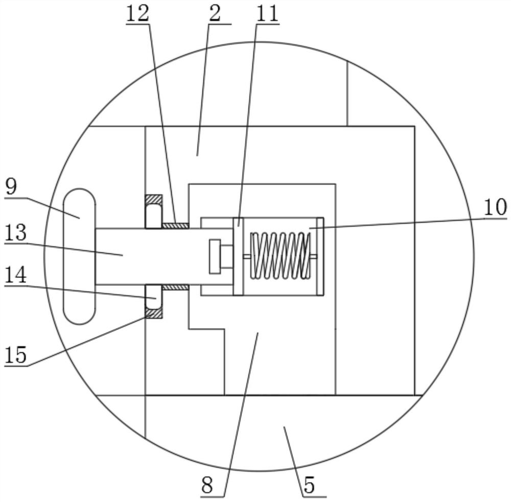
[0028] see Figure 1 to Figure 5 , the present invention provides a technical solution: a novel mica tape winding device, comprising a frame 1 and a substrate 5 arranged on the top of the frame 1, and the front surface of the substrate 5 is provided with a rotating shaft 3, and the surface of the rotating shaft 3 is provided with The inner baffle 7 and the outer baffle 4, the inner baffle 7 is fixedly connected with the rotating shaft 3, the outer baffle 4 is directly sleeved on the surface of the rotating shaft 3, the inner baffle 7 and the outer baffle 4 form a winding reel assembly, and the frame The top of 1 is symmetrically fixed with two struts 2 by bolts, the rear surface of the base plate 5 is symmetrically provided with two L-shaped sliders 8 by welding, and the interior of the struts 2 is provided with a matching L-shaped slider 8. L-shaped chute, the L-shaped slider 8 is inside the L-shaped chute, so that the L-shaped slider 8 can slide inside the L-shaped chute, th...


PUM


Abstract

The invention discloses a novel mica tape winding device which comprises a rack and a base plate arranged at the top of the rack, a rotating shaft is arranged on the front surface of the base plate, an inner side baffle disc and an outer side baffle disc are arranged on the surface of the rotating shaft, two supporting columns are symmetrically fixed to the top of the rack, two L-shaped sliding blocks are symmetrically arranged on the rear surface of the base plate, and the two L-shaped sliding blocks are symmetrically arranged on the base plate. An L-shaped sliding block is arranged in the supporting column, an L-shaped sliding groove matched with the L-shaped sliding block is formed in the supporting column, the L-shaped sliding block is located in the L-shaped sliding groove, a tension spring chamber is arranged in the L-shaped sliding block, the top end of the tension spring chamber is connected with an inner pulling plate, and a pulling rod is arranged on one side of the L-shaped sliding block. Through the arrangement of the L-shaped sliding block, the L-shaped sliding groove, the tension spring chamber, the inner pulling plate, the pulling rod, the pulling block, the strip-shaped sliding way, the side strip and the side clamping groove, the height of the base plate can be flexibly adjusted up and down, the overall adjusting mode is simpler and more convenient compared with an original device, and therefore convenience is brought to daily operation of operators.

Description

technical field [0001] The invention belongs to the technical field of mica tape processing equipment, and in particular relates to a novel mica tape winding device. Background technique [0002] The mica tape needs to go through multiple processes in the production and processing process, and needs to use a variety of equipment, including the need to use an automatic tape winding machine for automatic winding of the mica tape. This automatic tape winding machine is mainly composed of Composed of frame, rotating shaft, winding reel, motor and electric control box, it is mainly used for winding various tapes, labels, ribbons, paper and leather and other strip materials. [0003] During the use of the existing automatic tape winding machine, the motor and the winding reel are respectively arranged on the front and rear surfaces of the substrate, and the height of the rewinding reel can be changed by adjusting the height of the substrate. When adjusting, it is necessary to dis...

Claims


Application Information

Patent Timeline
Patent Type & Authority Applications(China)
IPC IPC(8): B65H18/10B65H18/00
CPCB65H18/10B65H18/00
Inventor 龙国和成志源
Owner HUAIHUA YONGGU ENERGY SAVING WALL MATERIAL
Why Eureka
Try Eureka