An electrical automation machining device

A technology of electrical automation and mechanical processing, applied in metal processing equipment, manufacturing tools, welding equipment, etc., can solve the problems of reduced cleanliness inside the body, entry into the body, and damage to the laser cutting head, so as to improve the flexibility of use and ensure Cleanliness, guarantee the effect of normal use

Inactive Publication Date: 2021-08-13
XIAN JIAOTONG UNIV CITY COLLEGE
View PDF7 Cites 0 Cited by
  • Summary
  • Abstract
  • Description
  • Claims
  • Application Information

AI Technical Summary

Problems solved by technology

[0004] 1. The laser cutting head at the bottom of the cutting machine base will continue to emit laser light during the operation of the equipment. After the equipment has been running for a period of time, the temperature on the surface of the laser cutting head will become higher and higher. If the machine is not shut down in time, it will affect the laser cutting head. The service life of the laser cutting head is long, and the existing laser cutting machine is not equipped with any device for sensing the surface temperature of the laser cutting head, so the operator can only judge whether the laser cutting head is high temperature through experience and the naked eye, the effect is not good, and laser cutting often occurs The problem of head damage;
[0005] 2. The surface of the body of the existing laser cutting machine has multiple cooling holes for heat dissipation inside the body, but because there is no blocking device, the cooling holes cannot be well shielded when the laser cutting machine is not in use. Foreign matter such as dust from the outside easily enters the inside of the body through the heat dissipation holes, resulting in a decrease in the cleanliness of the inside of the body, and it is easy to cause dust on the surface of the internal components of the body, which is inconvenient

Method used


Image

  • An electrical automation machining device
  • An electrical automation machining device
  • An electrical automation machining device

Examples


Embodiment

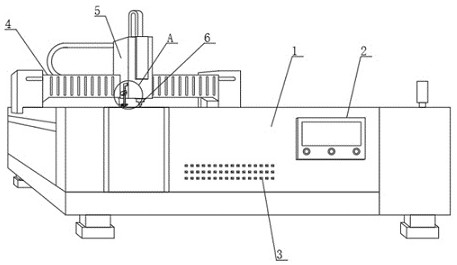
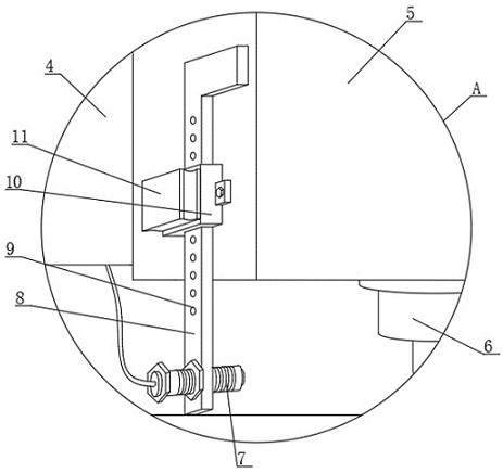
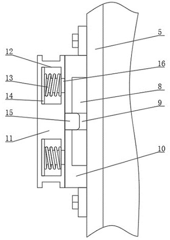
[0027] see Figure 1 to Figure 5 , the present invention provides a technical solution: an electrical automatic machining device, comprising a machine body 1 and a moving beam 4 arranged on the top of the machine body 1, and a cutting machine base 5 is slidably installed on the moving beam 4, and the bottom of the cutting machine base 5 A laser cutting head 6 is arranged at the end, and a temperature control mechanism is arranged on the cutting machine base 5. The temperature control mechanism includes a central control unit, a temperature control module, a display module and a temperature sensor 7. The temperature control module is connected with the central control unit, and the display module passes The data line is connected to the temperature control module, and the display module is also connected to the display screen 2 through the connection line for displaying temperature information. The temperature sensor 7 is connected to the data receiving module through the connec...


PUM


Abstract

The invention discloses an electrical automatic machining device, which comprises a machine body and a moving beam arranged on the top of the machine body, and a cutting machine base is slidably installed on the moving beam, and a laser cutting head is arranged at the bottom end of the cutting machine base. The cutting machine base is provided with a temperature control mechanism, the temperature control mechanism includes a central control unit, a temperature control module, a display module and a temperature sensor, the temperature control module is connected with the central control unit, and the display module is connected to the temperature control unit through a data line The temperature control module is connected to the control module; by setting the temperature control mechanism on the cutting machine base, the temperature control module can sense the surface temperature of the laser cutting head in real time. When the surface temperature of the laser cutting head is too high, the temperature control mechanism will send The box sends out a stop signal, causing the laser cutting machine to stop, thereby protecting the laser cutting head, and sending an alarm message through the alarm unit.

Description

technical field [0001] The invention belongs to the technical field of laser cutting equipment, and in particular relates to an electric automatic mechanical processing device. Background technique [0002] Electric automatic laser cutting machine is a kind of mechanical processing equipment, which focuses the laser emitted from the laser cutting head into a high-power density laser beam through the optical path system, and the laser beam irradiates the surface of the workpiece to make the workpiece reach the melting point or boiling point. The molten or vaporized metal is blown away by high-pressure gas coaxial with the beam. With the movement of the relative position of the beam and the workpiece, the material will eventually form a slit, so as to achieve the purpose of cutting. This electric automatic laser cutting machine is mainly composed of a body, a moving beam, a cutting machine base and a laser cutting head. The programming can automatically complete the cutting o...

Claims


Application Information

Patent Timeline
Patent Type & Authority Patents(China)
IPC IPC(8): B23K26/38B23K26/70B23K26/16
CPCB23K26/16B23K26/38B23K26/702
Inventor 张永超
Owner XIAN JIAOTONG UNIV CITY COLLEGE
Why Eureka
Try Eureka