
Fuel injection device with smoke exhaust function for diesel engine

A technology of fuel injection device and diesel engine, which is applied in the direction of fuel injection device, fuel injection control, engine control, etc. It can solve the problems of shortened service life, damage of combustion mechanism, insufficient fuel combustion, etc., so as to improve work efficiency and avoid damage , the effect of prolonging the service life

Inactive Publication Date: 2022-05-06
DONGTAI JIANDONG MACHINERY MFG
View PDF0 Cites 0 Cited by
  • Summary
  • Abstract
  • Description
  • Claims
  • Application Information

AI Technical Summary

Problems solved by technology

[0002] During the use of an existing fuel injection device for diesel engines with smoke exhaust function, when the temperature inside the combustion mechanism is high, there are certain safety hazards, and explosions may occur due to excessive temperatures. , causing certain damage to the engine and the operator, and when the temperature inside the combustion mechanism is low, the amount of fuel is not enough, which will cause certain damage to the combustion mechanism, thereby shortening the service life of the device. At the same time, the existing one has During the use of the fuel injection device for diesel engines with smoke exhaust function, the combustion of fuel is not sufficient, and more exhaust gas will be generated, which will cause certain damage to the environment and the body of the operator, and when the amount of fuel is small, it will cause The working efficiency of this engine is relatively low, therefore, it is very necessary to design a fuel injection device for diesel engines with smoke exhaust function to improve safety performance and prolong service life

Method used


Image

  • Fuel injection device with smoke exhaust function for diesel engine
  • Fuel injection device with smoke exhaust function for diesel engine
  • Fuel injection device with smoke exhaust function for diesel engine

Examples


Embodiment Construction

[0027] The following will clearly and completely describe the technical solutions in the embodiments of the present invention with reference to the accompanying drawings in the embodiments of the present invention. Obviously, the described embodiments are only some, not all, embodiments of the present invention. Based on the embodiments of the present invention, all other embodiments obtained by persons of ordinary skill in the art without making creative efforts belong to the protection scope of the present invention.

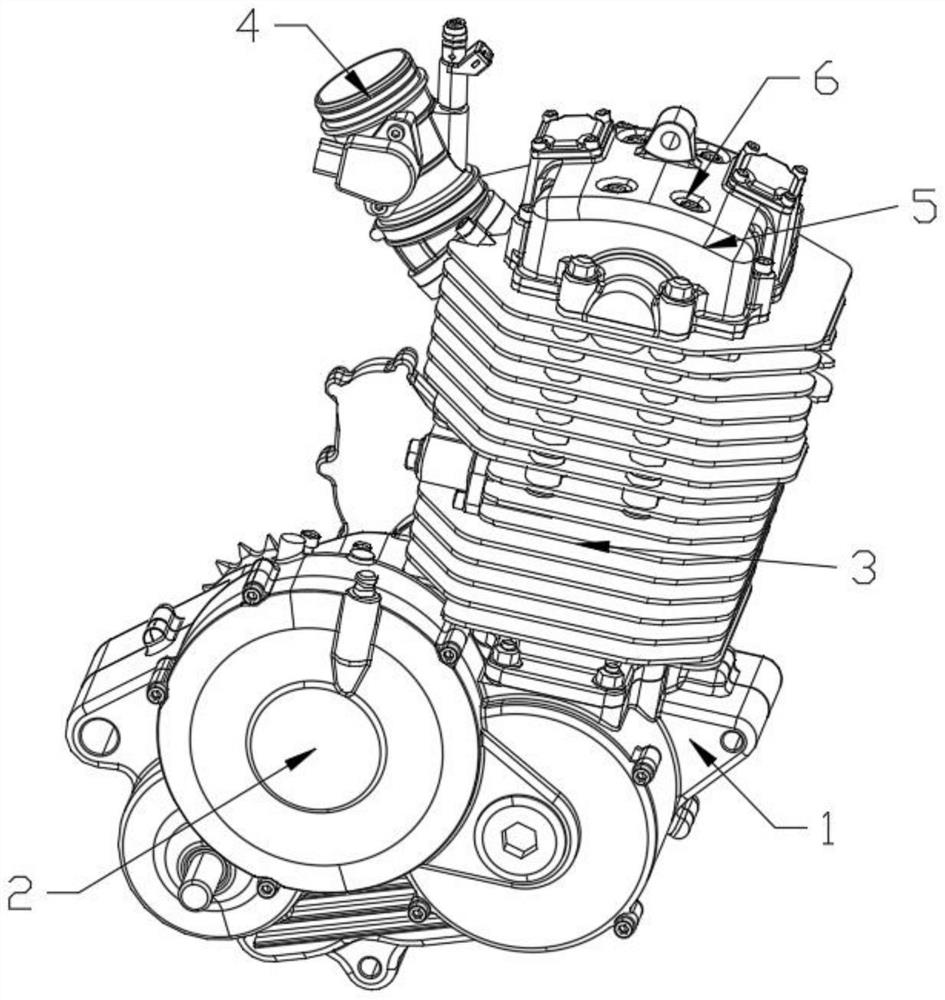
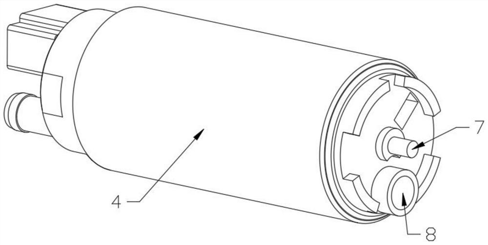
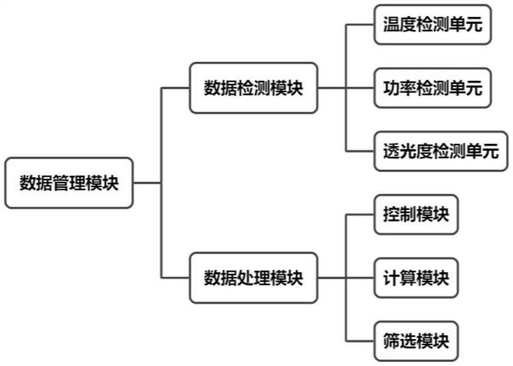
[0028] see Figure 1-3 The present invention provides a technical solution: a fuel injection device for a diesel engine with a smoke exhaust function, including an engine 1 and a data management module, the data management module includes a data detection module and a data processing module, and the data detection module is used to operate the device The real-time status in the process is detected, and the detected data information is transmitted to the data p...


PUM


Abstract

The invention discloses a diesel engine fuel injection device with a smoke exhaust function, which comprises an engine and a data management module, the data management module comprises a data detection module and a data processing module, the data detection module is used for detecting the real-time state of the device in the running process, and the data processing module is used for processing the real-time state of the device in the running process. The engine is used for detecting data information and transmitting the detected data information to the data processing module, the data processing module is used for analyzing and processing the received data information and controlling the device according to the processing result, an output mechanism is arranged on the outer side of the engine, and a combustion mechanism is arranged at the top of the engine. A left side pipeline of the combustion mechanism is connected with a material conveying pipe, a top pipeline of the combustion mechanism is connected with a smoke exhauster, the top of the smoke exhauster is provided with a plurality of groups of smoke exhaust ports, and the material conveying pipe is used for conveying fuel into the combustion mechanism.

Description

technical field [0001] The invention relates to the technical field of diesel engines, in particular to a fuel injection device for diesel engines with smoke exhaust function. Background technique [0002] During the use of an existing fuel injection device for diesel engines with smoke exhaust function, when the temperature inside the combustion mechanism is high, there are certain safety hazards, and explosions may occur due to excessive temperatures. , causing certain damage to the engine and the operator, and when the temperature inside the combustion mechanism is low, the amount of fuel is not enough, which will cause certain damage to the combustion mechanism, thereby shortening the service life of the device. At the same time, the existing one has During the use of the fuel injection device for diesel engines with smoke exhaust function, the combustion of fuel is not sufficient, and more exhaust gas will be generated, which will cause certain damage to the environment...

Claims


Application Information

Patent Timeline
IPC IPC(8): F02D41/30F02M63/00
CPCF02D41/30F02M63/00
Inventor 刘进刘嘉玲
Owner DONGTAI JIANDONG MACHINERY MFG
Learn More