
Engine cylinder cover and cylinder

A technology for engines and cylinder heads, applied in cylinder heads, engine components, machines/engines, etc., can solve the problems of single coolant and poor cooling effect of exhaust passages

Pending Publication Date: 2022-05-06
DONGFENG LIUZHOU MOTOR
View PDF8 Cites 0 Cited by
  • Summary
  • Abstract
  • Description
  • Claims
  • Application Information

AI Technical Summary

Problems solved by technology

[0003] The main purpose of the present invention is to provide an engine cylinder head and a cylinder, aiming at solving the problem that in the cooling process of the existing engine cylinder head, the coolant flows in a single direction, and successively contacts with multiple exhaust pipes in thermal contact, causing the last exhaust pipe to be exhausted. Technical problem with poor cooling effect

Method used


Image

  • Engine cylinder cover and cylinder
  • Engine cylinder cover and cylinder
  • Engine cylinder cover and cylinder

Examples


Embodiment Construction

[0035] The following will clearly and completely describe the technical solutions in the embodiments of the present invention with reference to the accompanying drawings in the embodiments of the present invention. Obviously, the described embodiments are only part of the embodiments of the present invention, not all of them. Based on the embodiments of the present invention, all other embodiments obtained by persons of ordinary skill in the art without creative efforts fall within the protection scope of the present invention.

[0036] It should be noted that if there are directional indications involved in the embodiment of the present invention, the directional indications are only used to explain the relative positional relationship, movement conditions, etc. between the components in a specific posture. If the specific posture changes , then the directional indication changes accordingly.

[0037] In addition, if there are descriptions involving "first", "second" and so o...


PUM


Abstract

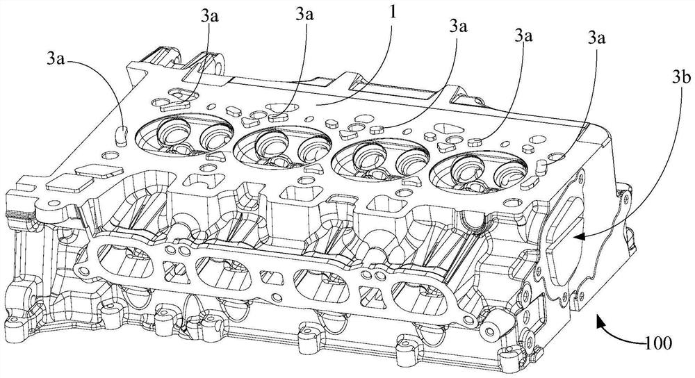
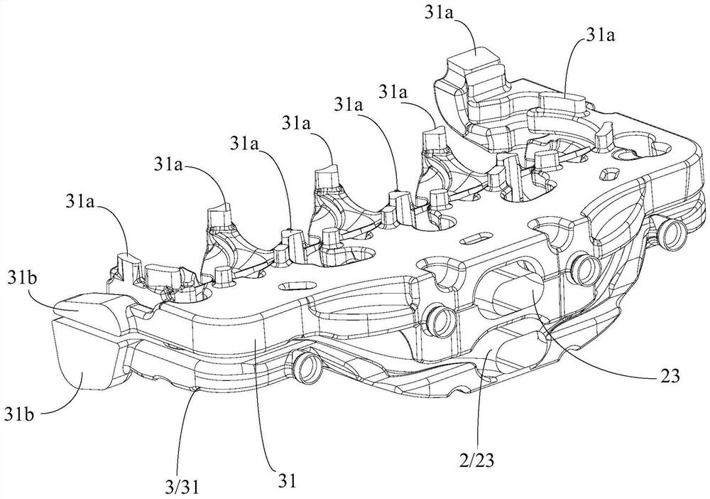
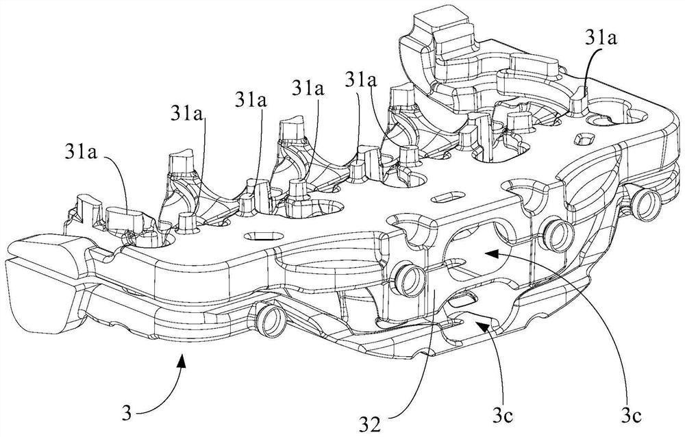
The engine cylinder cover comprises a shell, a plurality of exhaust pipelines and a cooling water jacket, the exhaust pipelines are arranged on the shell and arranged side by side in the length direction of the shell, and the cooling water jacket is arranged on the shell and makes thermal contact with the exhaust pipelines so as to dissipate heat of the exhaust pipelines. The cooling water jacket is provided with a water outlet and a plurality of water inlets, and the water inlets are arranged at intervals in the length direction of the shell. According to the scheme, the cooling water jacket is provided with the multiple water inlets, and the multiple water inlets are formed in the length direction of the shell at intervals, so that the problem that the cooling effect of the exhaust pipeline located behind the cooling liquid flowing direction is poor due to the fact that the temperature of the cooling liquid close to the water outlets is high due to the single flowing direction of the cooling liquid is solved. Specifically, in the scheme, the temperatures of the cooling liquid input from the water inlets near the exhaust pipelines are consistent and relatively low, so that heat dissipation of the exhaust pipelines is uniform, the heat dissipation effect of the exhaust pipelines is improved, and the service life of the engine is prolonged.

Description

technical field [0001] The invention relates to the technical field of engine equipment, in particular to an engine cylinder head and a cylinder. Background technique [0002] When the vehicle is running, the engine will generate high temperature due to continuous operation, so it needs to be cooled and dissipated to avoid damage to related components due to the high temperature generated. At present, during the cooling process of the cylinder head of the engine, the coolant flows in a single direction and is in thermal contact with multiple exhaust pipes in turn, resulting in poor cooling effect of the last exhaust pipe, so that the temperature inside the cylinder is still high, and the temperature of its related components is also low. High, the waste heat generated by combustion in the combustion chamber is dissipated through the surface of the cylinder, and the heat dissipation effect is not good, which affects the output power of the engine. Contents of the invention ...

Claims


Application Information

Patent Timeline
Patent Type & Authority Applications(China)
IPC IPC(8): F02F1/40F02F1/42
CPCF02F1/40F02F1/4264
Inventor 邓发平何道明潘永亮姚克甫马百坦吴振铭
Owner DONGFENG LIUZHOU MOTOR
Learn More