A control device for garden decorative lights

A technology for control devices and decorative lights, applied in lighting devices, lighting devices, fixed lighting devices, etc., can solve the problem that the integrity and firmness of soil cannot be improved, the function of resisting external force impact, and the inability to intercept, collect and reuse water, etc. problems, to achieve the effect of improving the integrity and improving the solidity

Active Publication Date: 2022-06-21
湖北欧鑫科技有限公司
View PDF10 Cites 0 Cited by
  • Summary
  • Abstract
  • Description
  • Claims
  • Application Information

AI Technical Summary

Problems solved by technology

[0004] In order to solve the above technical problems, the present invention provides a control device for garden decorative lights, which solves the problem that the existing control devices for garden decorative lights cannot improve the integrity and firmness of the soil, and do not have a certain resistance to external impact function, it cannot provide double protection against short-circuit and anti-pollution for the main body of the ball lamp, cannot guarantee the sensitivity of the sound-activated function of the sound-light control switch, cannot intercept, collect and reuse water, and cannot expand the contact between the bottom of the garden lamp and the soil area, thus making the overall installation more solid

Method used


Image

  • A control device for garden decorative lights
  • A control device for garden decorative lights
  • A control device for garden decorative lights

Examples


Embodiment 1

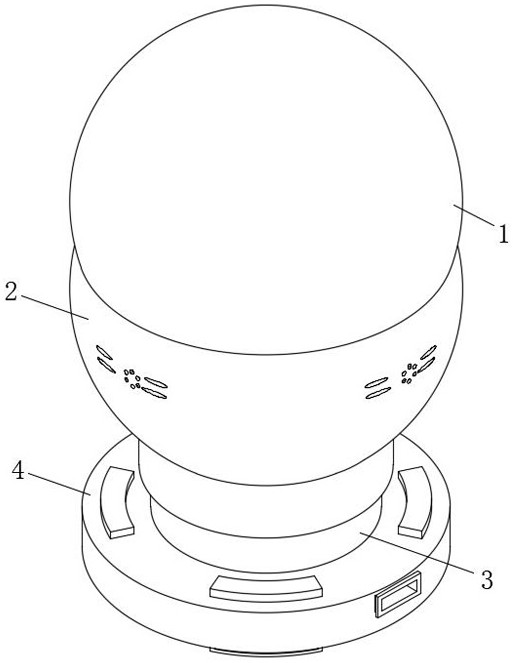
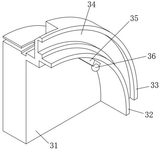
[0031] like Figure 1-Figure 6 As shown, the present invention provides a technical solution: comprising a garden lamp 1, an apron mechanism 2 is installed at the lower end of the garden lamp 1, a control opening mechanism 3 is installed at the inner middle position of the apron mechanism 2, and a buried opening mechanism 3 is installed at the lower end of the control opening mechanism 3. Assembly 4; the apron mechanism 2 includes an enclosing cover 21, the inner side wall surface of the enclosing cover 21 is provided with a first ring groove 22 near the upper part, the inner side of the first ring groove 22 is installed with a parallel pad 23, and the inner side wall of the enclosing cover 21 is provided with a first ring groove 22 A wall top block 24 is installed on the surface in a circular array; the upper end of the wall top block 24 is installed with an acousto-optic control switch 25, the acousto-optic control switch 25 is movably installed through the wall top block 24 ...

Embodiment 2

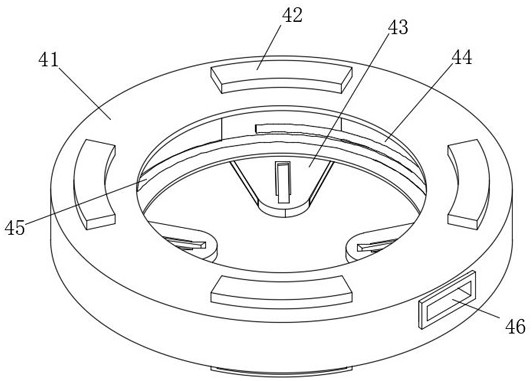
[0036] like figure 2 and Figure 4 As shown, the embedded component 4 includes an outer embedded ring 41, the upper end surface of the outer embedded ring 41 is installed with a convex-inch plate 42 in a circular array, and the lower end of the convex-inch plate 42 is installed with a movable tongue 43. An inner ring cavity 44 is opened on the inner side, a coil spring 45 is installed on the inner side of the inner ring cavity 44, and the tail end of the coil spring 45 is fixedly connected with the lower end of the outer buried ring 41 through the inner ring cavity 44; the outer surface of the outer buried ring 41 is opened There is a wire channel 46, and the convex plate member 42 includes an orientation plate 421. The surface of the orientation plate 421 is provided with a push-pull slot 422 through the middle position of the lower side. The two sides of the orientation plate 421 are symmetrically provided with an inner slot 423. The inner slot The inner middle position of...


PUM


Abstract

The invention discloses a control device for a garden decorative lamp, which comprises a garden lamp. An apron mechanism is installed at the lower end of the garden lamp. The corresponding cooperation between the ring rail cavity and the coil spring enables the outer ring to clamp the coil spring between the outer ring and the outer buried ring with the help of the inner ring cavity, and then the coil spring is limited as a whole through the lower ring wall The inner side of the inner ring cavity can effectively avoid derailment of the coil spring during the up and down bouncing process, and use the reverse rebound force generated after the coil spring is squeezed to quickly push the control opening mechanism together with the apron mechanism to the outer embedded ring The upper side of the bottom presses down through the bottom pressure plate to compact the soil at the bottom while improving the integrity and firmness of the soil.

Description

technical field [0001] The invention relates to the technical field of garden decoration, in particular to a control device for garden decoration lamps. Background technique [0002] Garden refers to a specific cultivated natural environment and recreational environment; using engineering technology and artistic means in a certain area, by transforming the terrain, or further building mountains, stacking stones, managing water, planting trees and flowers, building buildings and arranging garden roads, etc. The natural environment and recreational environment created are called gardens; it is unique in traditional Chinese architecture, and the major achievements are classical garden architecture. [0003] The existing control devices for garden decorative lights cannot improve the integrity and firmness of the soil, do not have a certain function of resisting external force impact, can not provide double protection against short-circuit and anti-pollution for the main body of...

Claims


Application Information

Patent Timeline
Patent Type & Authority Patents(China)
IPC IPC(8): F21S8/00F21V15/02F21V15/04F21V17/16F21V23/00F21V23/04F21V33/00A01M29/30A01M29/34
CPCF21S8/00F21V17/166F21V15/04F21V15/02F21V23/0442F21V33/00F21V23/001A01M29/34A01M29/30A01M2200/01
Inventor 郑磊肖鸿泽张琰炎董杰李威韩博文何家欢王恬
Owner 湖北欧鑫科技有限公司
Why Eureka
Try Eureka