Cutting equipment for automobile shock absorber spring

A technology of automobile shock absorber and cutting equipment, applied in the field of automobile shock absorber, can solve the problems of uneven cutting surface and deformation, and achieve the effect of improving processing efficiency

Inactive Publication Date: 2022-05-10
HUANGHE JIAOTONG UNIV
View PDF0 Cites 0 Cited by
  • Summary
  • Abstract
  • Description
  • Claims
  • Application Information

AI Technical Summary

Problems solved by technology

When cutting the end face of the existing shock absorber spring, usually only limit structures are provided at both ends to avoid displacement during the cutting process of the spring. When cutting with a knife and other structures, the end of the spring may be deformed due to lack of support, resulting in uneven cutting surface

Method used


Image

  • Cutting equipment for automobile shock absorber spring
  • Cutting equipment for automobile shock absorber spring
  • Cutting equipment for automobile shock absorber spring

Examples


Embodiment 1

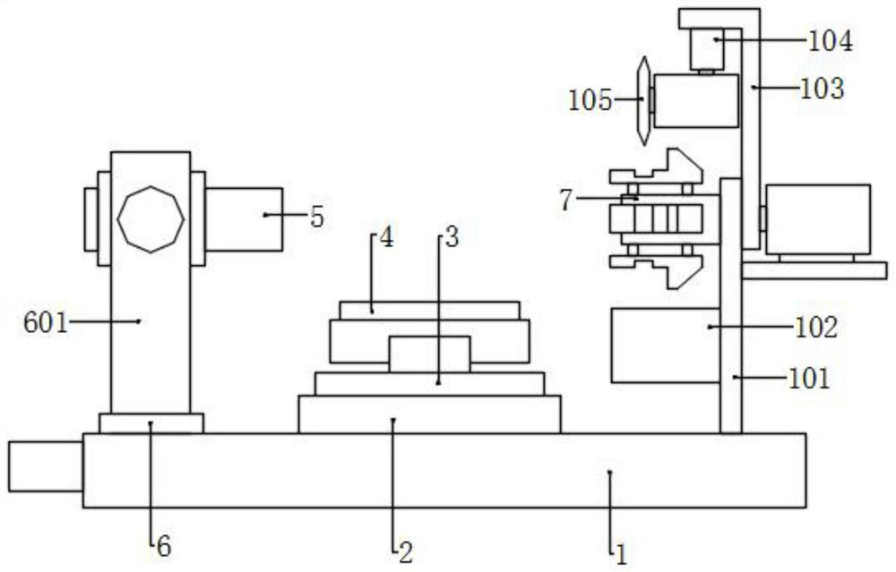
[0043] Please refer to accompanying drawing, the present invention provides a kind of technical scheme: a kind of cutting equipment that is used for automobile shock absorber spring, comprises workbench 1, and the top surface of workbench 1 is provided with first moving groove 106, and first moving groove 106 The middle slide is connected with a moving seat 2, the bottom of the moving seat 2 is connected with a first moving assembly, the top surface of the moving seat 2 is symmetrically provided with two rotating seats 3, and the rotating seat 3 is provided with a placement assembly;

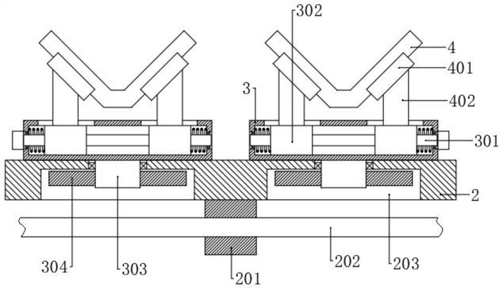
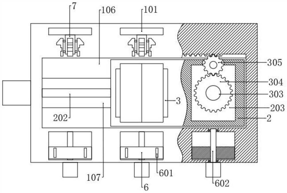
[0044] The center of the bottom surface of the rotating seat 3 is fixed with a rotating shaft 303, and the bottom of the moving seat 2 is correspondingly provided with two rotating grooves 203. The rotating shaft 303 is connected to the top of the rotating groove 203 in rotation, and the bottom end is fixed with a first gear 304. One side of a gear 304 is meshed with a second gear 305, and the si...

Embodiment 2

[0050] The structure of this embodiment is basically the same as that of Embodiment 1, the difference is that the placement assembly includes two support columns 401 symmetrically arranged on the top surface of the rotating seat 3, and the top surfaces of the two support columns 401 are connected with a V-shaped placement Seat 4, the two top surfaces of placing seat 4 are respectively provided with T-shaped spring grooves, and the spring block 405 of corresponding shape is slidably connected in the spring groove, and the two ends of spring block 405 and the two ends of spring groove respectively A spring is connected, and the outer ends of the two spring blocks 405 are jointly fixed with a V-shaped spring plate 404 .

[0051] When the shock absorber spring is placed on the spring plate 404 on the placement seat 4, the positioning assembly 5 pushes the shock absorber spring, so that the spring plate 404 moves relative to the placement seat 4, so that the other end of the shock a...

Embodiment 3

[0057] The structure of this embodiment is basically the same as that of Embodiment 1, the difference is that the rotating assembly includes a rotating box 501 located between the upper parts of the two side plates 601, and connecting cylinders are symmetrically fixed on the two side walls of the rotating box 501, and in the connecting cylinder A fixed cylinder 603 is rotatably connected, and the two ends of the fixed cylinder 603 extend into the inside of the rotating box 501, and are jointly connected with a fixed shell 604, and the fixed shell 604 is provided with a third moving assembly, and the outer end of the fixed cylinder 603 extends out to rotate box 501, and is fixedly connected with the corresponding side plate 601, a first ring gear 502 is fixed on one of the connecting cylinders, the bottom of the first ring gear 502 is engaged with a rotating gear 507, and the rotating gear 507 is connected with a motor, when it is necessary to use When the positioning assembly 5...


PUM


Abstract

The invention discloses cutting equipment for an automobile shock absorber spring in the technical field of automobile shock absorbers, and the cutting equipment comprises a workbench and a moving seat, three groups of positioning assemblies and supporting assemblies are arranged on the workbench, the positioning assemblies are connected with rotating assemblies, cutting assemblies are arranged at the supporting assemblies, and two rotating seats are arranged on the moving seat. According to the shock absorber spring cutting device, feeding is conducted through the positioning assembly in the middle, shock absorber springs are positioned through the positioning assembly and the supporting assembly, the supporting assembly supports the cutting ends of the shock absorber springs, and the problems that when the ends of the shock absorber springs are cut, deformation occurs due to lack of supporting, and the cutting quality is affected are avoided; by arranging the three positioning assemblies and the supporting assemblies and arranging the two rotating seats on the moving seat, the moving seat reciprocates in the first moving groove, so that feeding, feeding and two times of cutting machining are repeatedly conducted, the two rotating seats work at the same time, and the machining efficiency is improved.

Description

technical field [0001] The invention relates to the technical field of automobile shock absorbers, in particular to a cutting device for automobile shock absorber springs. Background technique [0002] In order to quickly attenuate the vibration of the frame and body and improve the ride comfort and comfort of the car, the suspension system of the car is generally equipped with a shock absorber, and the two-way acting barrel shock absorber is widely used in the car. After the spring of the shock absorber is wound and processed, the two ends of the spring have helical rise angles, and the two ends of the spring need to be cut to make the ends flat so that they can be stably installed on the corresponding structure of the shock absorber. When cutting the end face of the existing shock absorber spring, usually only limit structures are provided at both ends to avoid displacement during the cutting process of the spring. When cutting with a structure such as a knife, the end of...

Claims


Application Information

Patent Timeline
Patent Type & Authority Applications(China)
IPC IPC(8): B21F11/00B21F23/00
CPCB21F11/005B21F23/00
Inventor 曹镇杭姚会君员浩然
Owner HUANGHE JIAOTONG UNIV
Why Eureka
Try Eureka