A kind of mold blank cutting equipment and cutting method thereof

A technology of cutting equipment and blanks, which is applied in the direction of separation methods, chemical instruments and methods, and the use of liquid separation agents, etc., can solve the problems of poor environment in the cutting workshop, increased labor, and inability to deal with smoke and particles, so as to avoid overheating and improve cutting efficiency. Effect, the effect of avoiding the spread of harmful smoke

Active Publication Date: 2021-08-10
佛山市顺德区水艺源五金模具有限公司
View PDF9 Cites 0 Cited by
  • Summary
  • Abstract
  • Description
  • Claims
  • Application Information

AI Technical Summary

Problems solved by technology

[0004] The Chinese invention with the patent number CN201711352885.1 in the prior art discloses a part cutting equipment for mold processing. A connecting plate is fixedly connected to the side wall of the cutting device, and a water inlet pipe is arranged on the connecting plate. The lower end of the water inlet pipe is There is a nozzle connected, and the cooling liquid is poured into the water inlet pipe during cutting, and the cooling liquid is sprayed out from the nozzle to cool down the mold, but the smoke and particles generated during cutting cannot be treated, which makes the environment of the cutting workshop relatively poor. Difference
[0005] The Chinese invention with the patent number CN201911387140.8 in the prior art discloses an environmental protection cutting device. An air pump is installed on the top of the cutting cabinet of the device, and the air pump is extended and installed on the inner top of the cutting cabinet. The gas blown by the air pump After spraying through the air pipe, an air wall is formed. The air wall can prevent the smoke and particles generated during cutting from flying out of the cutting cabinet, ensuring the working environment of the workshop. However, if the time is too long, a large amount of smoke and waste will remain in the cabinet, requiring additional Increase labor to clean up and increase labor intensity

Method used


Image

  • A kind of mold blank cutting equipment and cutting method thereof
  • A kind of mold blank cutting equipment and cutting method thereof
  • A kind of mold blank cutting equipment and cutting method thereof

Examples


Embodiment 1

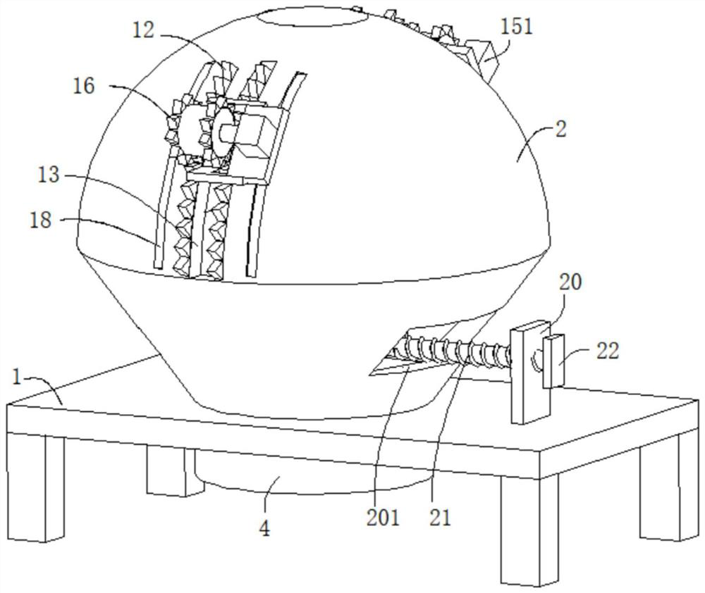
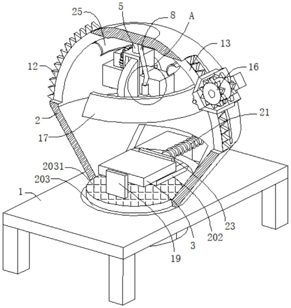
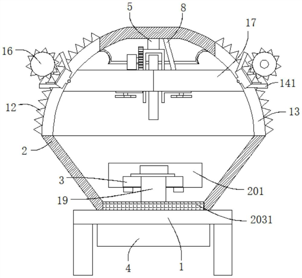
[0039] refer to figure 1 , figure 2 , Figure 5 and Figure 7 , a mold blank cutting equipment and cutting method thereof, comprising a frame 1, the top of the frame 1 is connected with a shell 2, the outer wall of the shell 2 is dug with an outlet 201, the inner wall of the shell 2 is connected with a fixed plate 202, and the fixed plate 202 The top of the frame 1 is movably connected with a workpiece 3, the bottom of the housing 2 is dug with a through hole 203, the inner wall of the through hole 203 is connected with a filter screen 2031, the bottom wall of the frame 1 is connected with a water storage tank 4, and the water storage tank 4 and the through hole 203 Interconnected, the top of the housing 2 is connected with the fixed shaft 5, the bottom of the fixed shaft 5 is connected with the fixed frame 501, the fixed frame 501 is connected with the first rotating shaft 502 for rotation, the outer wall of the first rotating shaft 502 is connected with the cutting tool 5...

Embodiment 2

[0042] refer to figure 1 , figure 2 , image 3 , Figure 4 and Image 6 , a mold blank cutting device and its cutting method are basically the same as in Embodiment 1, and furthermore, the outer walls on both sides of the housing 2 are connected with a rack group 12, and the rack group 12 includes two racks, and the housing 2 The outer wall is dug with a concave hole 13, the concave hole 13 is placed between two racks, the inner wall of the concave hole 13 is movably connected with a moving block 14, the bottom wall of the moving block 14 is connected with a scraper 17 through a hinge, and the two scrapers 17 It is offset against the inner wall of the housing 2, and the two scrapers 17 are fixedly connected. Both sides of the outer wall of the moving block 14 are connected with connecting plates 141. The ends of the two connecting plates 141 away from the moving block 14 are connected with a placement plate 15. The placement plate 15 The outer wall is connected with a sec...

Embodiment 3

[0045] refer to figure 2 and Figure 8 , a mold blank cutting device and its cutting method are basically the same as in Embodiment 1, furthermore, the outer wall of the filter screen 2031 is connected with a first splint 19, and the outer wall of the first splint 19 is connected with a telescopic rod 191, and the telescopic rod 191 is far away from One end of the first splint 19 is connected with a force plate 192, the outer wall of the telescopic rod 191 is sleeved with a first elastic element 193, the first elastic element 193 is placed between the first splint 19 and the force plate 192, and the outer wall of the frame 1 is connected There is a positioning plate 20, the internal thread of the positioning plate 20 is connected with a screw rod 21, the outer wall of the screw rod 21 is connected with a handle 22, and the end of the screw rod 21 away from the handle 22 is connected with a second splint 23, the second splint 23 is moved against the workpiece 3, and the force ...


PUM


Abstract

The invention discloses a mold blank cutting device and a cutting method thereof, belonging to the technical field of mold processing equipment. A mold blank cutting equipment, comprising a frame, the top of the frame is connected with a shell, the outer wall of the shell is dug with an outlet, the inner wall of the shell is connected with a fixed plate, the top of the fixed plate is movably connected with a processing part, and the bottom of the shell is dug There is a through hole, the inner wall of the through hole is connected with a filter screen, the bottom wall of the frame is connected with a water storage tank, the water storage tank and the through hole are connected to each other, the top of the housing is connected with a fixed shaft, and the bottom of the fixed shaft is connected with a fixed frame. A first rotating shaft is rotatably connected in the frame, and a cutting tool is connected to the outer wall of the first rotating shaft. Waste debris and harmful smoke are scattered everywhere, which is conducive to the progress of environmental protection work, thereby ensuring the working environment of the staff and ensuring the health of the staff.

Description

technical field [0001] The invention relates to the technical field of mold processing equipment, in particular to a mold blank cutting equipment and a cutting method thereof. Background technique [0002] Molds, various molds and tools used in industrial production for injection molding, blow molding, extrusion, die-casting or forging forming, smelting, stamping, etc. to obtain the required products, in short, molds are tools used to make shaped objects , This tool is composed of various parts, and different molds are composed of different parts. It mainly realizes the processing of the shape of the object through the change of the physical state of the formed material, known as the "mother of industry". [0003] Under the action of external force, the blank becomes a tool with a specific shape and size. It is widely used in blanking, die forging, cold heading, extrusion, powder metallurgy parts pressing, pressure casting, and engineering plastics, rubber, ceramics and othe...

Claims


Application Information

Patent Timeline
Patent Type & Authority Patents(China)
IPC IPC(8): B26D7/02B01D47/06B26D5/08B26D7/08B26D7/18
CPCB26D7/02B26D5/086B26D7/08B26D7/18B26D7/1854B01D47/06Y02P70/10
Inventor 不公告发明人
Owner 佛山市顺德区水艺源五金模具有限公司
Why Eureka
Try Eureka