
Shaft part surface deburring method

A technology for shaft parts and deburring, which is applied in the direction of grinding workpiece supports, parts of grinding machine tools, and machine tools suitable for grinding workpiece edges. Problems such as low production efficiency, to achieve the effect of improving processing quality, convenient adjustment, and improving efficiency

Pending Publication Date: 2022-05-10
吴招娣
View PDF5 Cites 0 Cited by
  • Summary
  • Abstract
  • Description
  • Claims
  • Application Information

AI Technical Summary

Problems solved by technology

The current method is to manually use a file to remove it manually. In the existing removal method, workers need to manually polish multiple parts on each part, and the production efficiency is very low. Due to the large output of parts, it takes a lot of time The work is done manually, and the manual operation is greatly affected by the workers' own conditions, so the quality of burr removal cannot be guaranteed

Method used


Image

  • Shaft part surface deburring method
  • Shaft part surface deburring method
  • Shaft part surface deburring method

Examples


Embodiment Construction

[0040] The present invention will be further explained below in conjunction with the accompanying drawings and specific embodiments. It should be understood that the following specific embodiments are only used to illustrate the present invention and are not intended to limit the scope of the present invention.

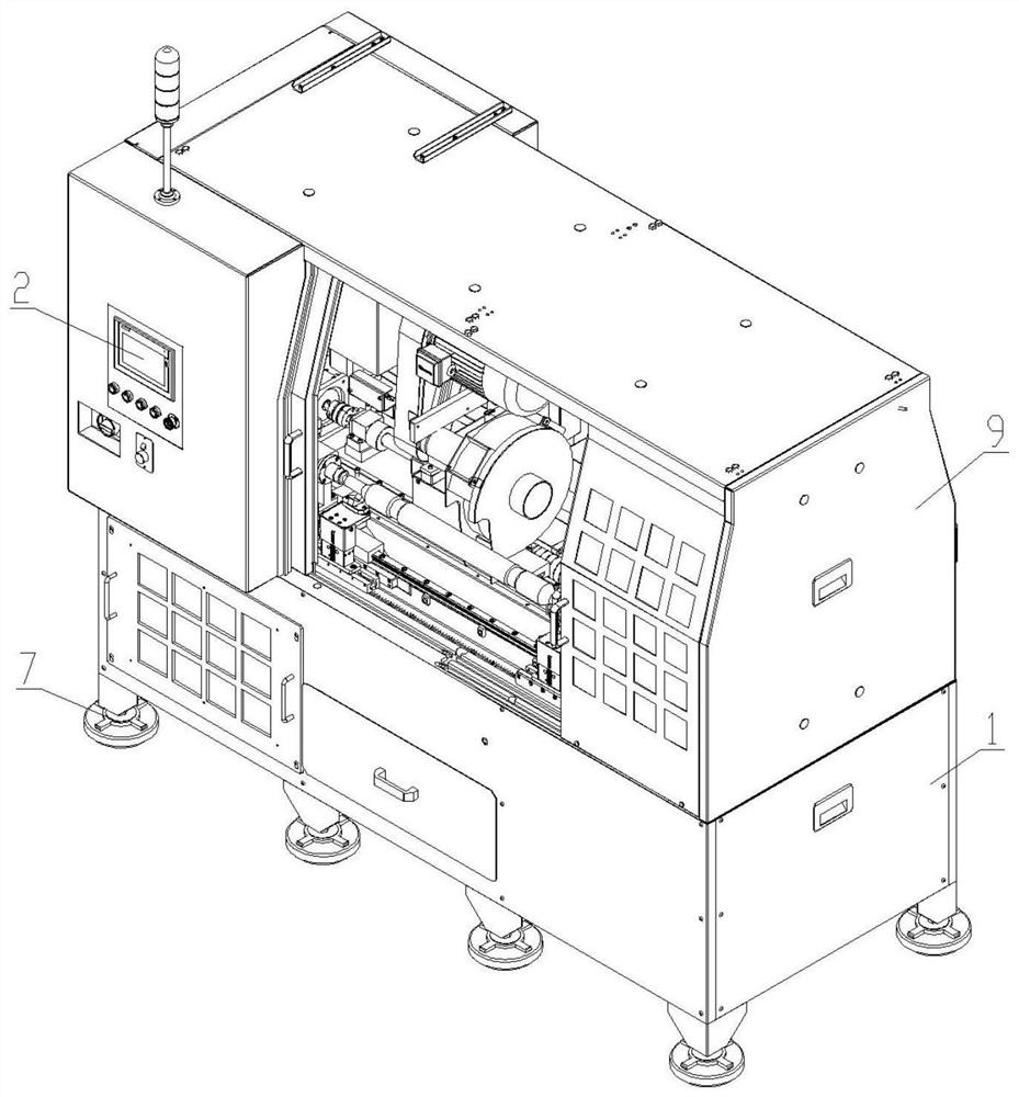
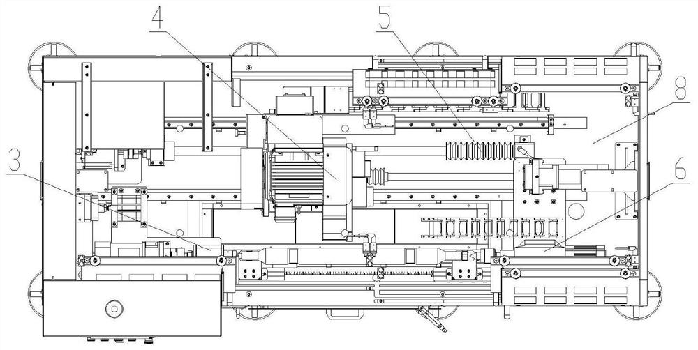
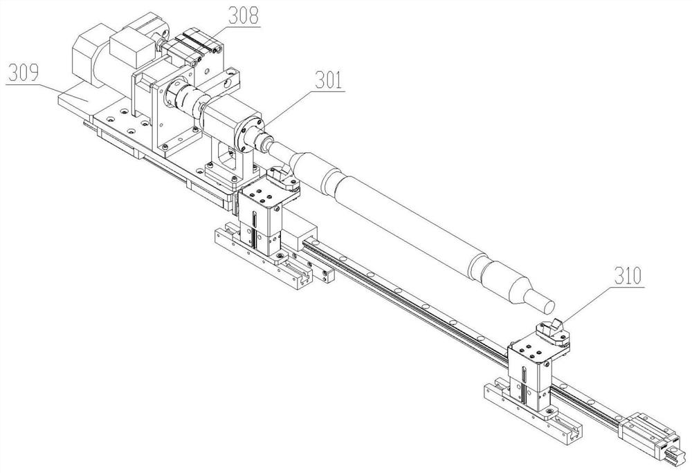
[0041] see figure 1 , 2 As shown, the present invention discloses a surface deburring device for shaft parts, including a frame 1, a control panel 2, a shaft part clamping mechanism 3, a grinding assembly 4, a moving assembly 5, a clamping mechanism 6 and a PLC controller , the bottom of the frame 1 is fixed with a disc leg 7, the top of the frame 1 is provided with a workbench 8, the outside of the workbench 8 is provided with a casing 9, and a control panel 2 is installed on the casing 9 , the middle part of the workbench 8 is provided with a moving assembly 5, a grinding assembly 4 is installed on the moving assembly 5, and a shaft part clamping mechanism 3 is pro...


PUM


Abstract

The invention relates to a shaft part surface deburring method which mainly solves the problems that manual operation is greatly influenced by the conditions of workers and the deburring quality cannot be guaranteed. The shaft part surface deburring device comprises a rack, a control panel, a shaft part clamping mechanism, a grinding assembly, a moving assembly, a clamping mechanism and a PLC, disc supporting legs are fixed to the bottom of the rack, a workbench is arranged on the top of the rack, the workbench is covered with a cover shell, and the cover shell is arranged on the top of the rack. A housing is arranged on the workbench, a control panel is installed on the housing, a moving assembly is arranged in the middle of the workbench, a grinding assembly is installed on the moving assembly, a shaft part clamping mechanism is arranged on one side of the moving assembly, a clamping mechanism is arranged at one end of the shaft part clamping mechanism, and the control panel is electrically connected with a PLC. The problem is well solved, and the shaft part machining tool can be used for machining shaft parts.

Description

technical field [0001] The invention relates to the technical field of shaft parts processing, in particular to a method for deburring the surface of shaft parts. Background technique [0002] Shaft parts are an important part of the engine. During the production process, the burrs generated in the previous process need to be removed. The current method is to manually use a file to remove it manually. In the existing removal method, workers need to manually polish multiple parts on each part, and the production efficiency is very low. Due to the large output of parts, it takes a lot of time The work is carried out manually, and the manual operation is greatly affected by the condition of the workers themselves, so the quality of deburring cannot be guaranteed. Therefore, there is an urgent need to develop a surface deburring device for shaft parts that can solve the above problems. Contents of the invention [0003] The invention provides a method for deburring the surfa...

Claims


Application Information

Patent Timeline
IPC IPC(8): B24B9/04B24B41/06B24B41/02B24B27/02B24B47/12B24B47/06
CPCB24B9/04B24B41/061B24B41/02B24B27/02B24B47/12B24B47/06
Inventor 吴招娣
Owner 吴招娣
Learn More