Unlock instant, AI-driven research and patent intelligence for your innovation.
Movement mechanism and mechanical equipment
What is Al technical title?
Al technical title is built by PatSnap Al team. It summarizes the technical point description of the patent document.
A technology of motion mechanism and rotating parts, which is applied in the field of mechanical motion, can solve problems such as low work efficiency, and achieve the effect of speeding up and improving work efficiency
Inactive Publication Date: 2022-05-10
厦门威芯泰科技有限公司
View PDF0 Cites 0 Cited by
Summary
Abstract
Description
Claims
Application Information
AI Technical Summary
This helps you quickly interpret patents by identifying the three key elements:
Problems solved by technology
Method used
Benefits of technology
Problems solved by technology
[0003] The purpose of the present invention is to overcome the working position on the rotating mechanism existing in the background technology. When the rotating mechanism rotates, the working position also rotates synchronously, causing the shape of the working position to change before and after the rotation. When the position needs to work in the same shape after rotation, the user needs to adjust the turned work position to make it consistent with the shape of the work position before the rotation, resulting in multiple mechanisms and low work efficiency. , providing a motion mechanism and mechanical equipment
Method used
Image
Click on the blue label to locate the original text in one second.
Reading with bidirectional positioning of images and text.
Examples
Embodiment 1
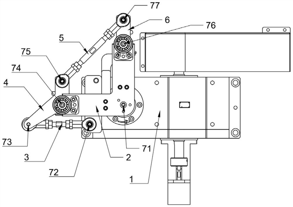
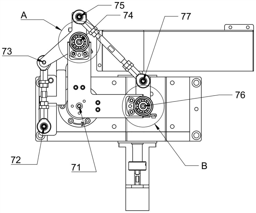
[0052] refer to figure 1 , figure 2 , a motion mechanism, the motion mechanism includes a base 1, a first rotating member 2, a first connecting rod 3, a second rotating member 4, a second connecting rod 5, a third rotating member 6 and a transmission member.
[0053] The base 1, the base 1 is provided with an accommodating cavity, the transmission part is placed in the accommodating cavity and is used to control the lifting and rotating movement of the first rotating part 2, and the transmission part is located in the base 1 to protect the transmission part;
[0054] The first rotating member 2 slides relative to the base 1 along the direction of the first axis 71, rotates relative to the base 1 around the first axis 71, is connected to the second rotating member 4 around the fourth axis 74, and rotates around the sixth axis. 76 is rotatably connected to the third rotating member 6;
[0055] Specifically, the first rotating part 2 is provided with a lifting rotating shaft, ...
Embodiment 2
[0070] A mechanical device, including a feed line, a detection line, a discharge line and the above-mentioned motion mechanism, the feed line is provided with a first station, the detection line is provided with a second station, and the discharge line is provided with a third station, And both the first working station and the second working station are equipped with manipulators for relay transfer, wherein the position of the first station corresponds to the first position, the position of the second station corresponds to the second position, and the third The position of the workstation corresponds to the third position. In this embodiment, the mechanical equipment is used for relay transfer, because it is understood that, according to the usage scenario, the first station, the second station and the third station may also be processing stations, testing stations, etc.
[0071] The relay is a cuboid, if it is transported along the wide side, it is easy to fall down, so the...
PUM
Abstract
The invention discloses a movement mechanism and mechanical equipment, and the movement mechanism comprises a base, a first rotating part, a first connecting rod, a second rotating part, a second connecting rod and a third rotating part, and a first working position of the second rotating part and a second working position of the third rotating part can be located at a second position. Therefore, the work station corresponding to the second position can be operated. The connecting line of the first axis and the second axis is parallel to the connecting line of the third axis and the fourth axis, and the connecting line of the first axis and the fourth axis is parallel to the connecting line of the third axis and the second axis; the connecting line of the fourth axis and the fifth axis is parallel to the connecting line of the sixth axis and the seventh axis, and the connecting line of the fourth axis and the sixth axis is parallel to the connecting line of the fifth axis and the seventh axis, so that it is guaranteed that the shapes of the first working position and the second working position are not changed, and the working efficiency is improved.
Description
technical field [0001] The invention relates to the field of mechanical motion, in particular to a motion mechanism and mechanical equipment. Background technique [0002] The working position on the rotating mechanism, when the rotating mechanism rotates, the working position also rotates synchronously, resulting in the change of the shape of the working position before and after the rotation. When working, the user needs to adjust the rotating working position to make it consistent with the shape of the working position before rotating, resulting in multiple mechanisms and low working efficiency. Contents of the invention [0003] The purpose of the present invention is to overcome the working position on the rotating mechanism existing in the background technology. When the rotating mechanism rotates, the working position also rotates synchronously, causing the shape of the working position to change before and after the rotation. When the position needs to work in the...
Claims
Application Information
Patent Timeline
Application Date:The date an application was filed.
Publication Date:The date a patent or application was officially published.
First Publication Date:The earliest publication date of a patent with the same application number.
Issue Date:Publication date of the patent grant document.
PCT Entry Date:The Entry date of PCT National Phase.
Estimated Expiry Date:The statutory expiry date of a patent right according to the Patent Law, and it is the longest term of protection that the patent right can achieve without the termination of the patent right due to other reasons(Term extension factor has been taken into account ).
Invalid Date:Actual expiry date is based on effective date or publication date of legal transaction data of invalid patent.
