
Actuating device for clutch device, clutch device having such actuating device, and method for producing such actuating device

A technology of clutches and double clutches, applied in fluid pressure actuators, clutches, fluid-driven clutches, etc., can solve problems such as laborious manufacturing and achieve reliable positioning and centering

Pending Publication Date: 2022-05-10
BORGWARNER INC
View PDF0 Cites 0 Cited by
  • Summary
  • Abstract
  • Description
  • Claims
  • Application Information

AI Technical Summary

Problems solved by technology

[0003] Known hydraulic actuation devices for clutch devices have proven relatively labor-intensive to manufacture, although improvements are needed

Method used


Image

  • Actuating device for clutch device, clutch device having such actuating device, and method for producing such actuating device

Examples


Embodiment Construction

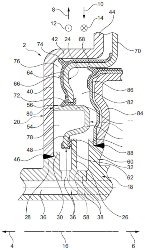
[0030] figure 1 A hydraulic actuation device 2 is shown for use in a clutch arrangement of a drive train of a motor vehicle. exist figure 1 , the mutually opposite axial directions 4, 6, the mutually opposite radial directions 8, 10 and the mutually opposite circumferential directions 12, 14 of the actuating device 2 or the clutch arrangement are indicated by means of corresponding arrows, wherein the actuating device 2 Or the clutch device is rotatable in the circumferential direction 12 , 14 about a rotational axis 16 extending in the axial direction 4 , 6 . The two axial directions 4 , 6 are also referred to below as the first axial direction 4 and the second axial direction 6 .

[0031] The actuating device 2 essentially consists of a hub 18 , a first housing part 20 , a second housing part 22 and an actuating piston 24 . The hub 18 is substantially tubular and extends in the axial direction 4 , 6 . In this case, the hub 18 is preferably used as an optionally input-sid...


PUM


Abstract

The invention relates to a hydraulic actuating piston (24) for a clutch device, comprising an actuating piston (24), a piston chamber (76) which corresponds to the actuating piston, and a supply chamber (78) which is arranged further inward in the radial direction (10) than the piston chamber (76) and via which hydraulic fluid can be fed to the piston chamber (76), wherein the supply chamber (78) is delimited in a first axial direction (4) by a first housing part (20) and in a second axial direction (6) opposite the first axial direction (4) by a second housing part (22), and the first housing part (20) is fastened to a hub (18). The first housing part (20) is fastened to the hub (18) by clamping the second housing part (22) between the first housing part (20) and the hub (18) in the axial direction (4, 6). The invention further relates to a clutch device having such an actuating device (2) and to a method for producing such an actuating device (2).

Description

technical field [0001] The current invention relates to a hydraulically actuated piston for a clutch device having an actuating piston, a piston chamber corresponding to said actuating piston and a A supply chamber capable of supplying hydraulic fluid to the piston chamber, wherein the supply chamber is bounded in a first axial direction by the first housing part and in a second axial direction opposite to the first axial direction by the second The housing part delimits, and the first housing part is fastened to the hub. Furthermore, the invention relates to a clutch arrangement having such an actuating device. The invention also provides a method for manufacturing such a hydraulic actuator. Background technique [0002] Hydraulic actuation devices in clutch arrangements, such as multi-plate clutches, are known in practice. In this case, the known actuating device essentially consists of an actuating piston, a first housing part, a second housing part and a hub, which ca...

Claims


Application Information

Patent Timeline
Patent Type & Authority Applications(China)
IPC IPC(8): F16D25/0635F16D25/0638F16D25/10F16D25/12
CPCF16D25/0635F16D25/0638F16D25/10F16D25/14F16D25/12F16D25/083F16D2250/0076F16D2250/0015F16D2250/0023F16D2200/0021F15B2201/60F15B2215/30F16D2125/02
Inventor D·梅耶尔
Owner BORGWARNER INC
Learn More