Visual tracking method and device, equipment and storage medium
A visual tracking and seed technology, applied in the field of computer vision, can solve the problems of tracking target loss, affecting the tracking effect, affecting the calculation of the tracking algorithm, etc., to achieve the effect of improving the tracking effect.
- Summary
- Abstract
- Description
- Claims
- Application Information
AI Technical Summary
Problems solved by technology
Method used
Image

Examples
Embodiment 1
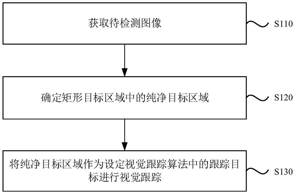
[0068] figure 1 Embodiment 1 of the present invention provides a flow chart of a visual tracking method. This embodiment is applicable to the situation of tracking a target object in an image. The method can be executed by a visual tracking device, which can adopt Realized in the form of hardware and / or software, the visual tracking device can be configured in electronic equipment. Such as figure 1 As shown, the method includes:
[0069] S110. Acquire an image to be detected.
[0070] Wherein, the image to be detected includes a rectangular target area.
[0071] In this embodiment, the rectangular target area may be an artificially marked area containing the target object to be tracked. For a given frame of image to be detected, it usually contains two parts: the rectangular target area T r and the background area B around the target object r . Preferably, the rectangular target area T r It can be obtained by manually marking a rectangular bounding box in the first fra...
Embodiment 2
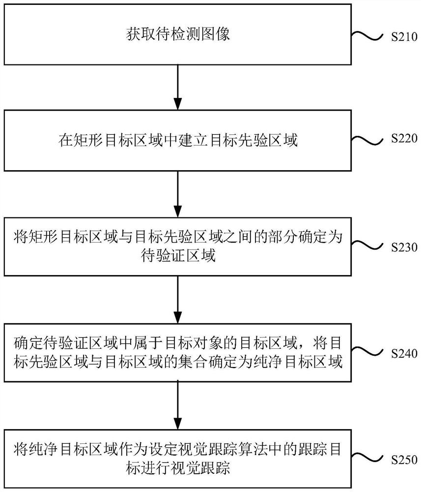
[0082] figure 2 It is a flow chart of a visual tracking method provided by Embodiment 2 of the present invention, and this embodiment is a refinement of S120 in the above-mentioned embodiment. Such as figure 2 As shown, the method includes:
[0083] S210. Acquire an image to be detected.
[0084] Wherein, the image to be detected includes a rectangular target area.
[0085] In this embodiment, the image to be detected may be obtained by obtaining a video sequence to be detected, and the rectangular target area may be determined in the image to be detected by manually marking or the like.
[0086] S220. Establish a target prior area in the rectangular target area.
[0087] Wherein, the target prior area is an area included in the rectangular target area and smaller in area than the rectangular target area.
[0088] In this embodiment, since the rectangular target area contains part of the background area, by setting a smaller target prior area, the background area contai...
Embodiment 3
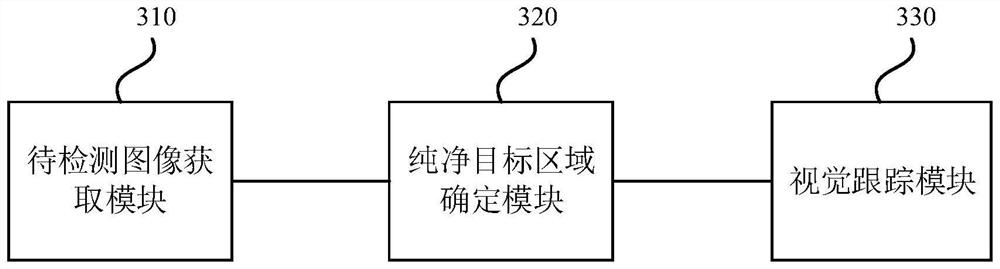
[0120] image 3 It is a schematic structural diagram of a vision tracking device provided by Embodiment 3 of the present invention. Such as image 3 As shown, the device includes: an image acquisition module 310 to be detected, a pure target area determination module 320 and a visual tracking module 330 .
[0121] The image to be detected acquisition module 310 is configured to acquire an image to be detected.
[0122] Wherein, the image to be detected includes a rectangular target area.
[0123] The clean target area determination module 320 is configured to determine a clean target area in the rectangular target area.
[0124] The visual tracking module 330 is configured to use the pure target area as the tracking target in the set visual tracking algorithm to perform visual tracking.
[0125] Optionally, the pure target area determination module 320 is also used for:
[0126] Establish the target prior area in the rectangular target area; determine the part between the...
PUM
 Abstract
Description
Claims
Application Information
 - R&D
- Intellectual Property
- Life Sciences
- Materials
- Tech Scout
- Unparalleled Data Quality
- Higher Quality Content
- 60% Fewer Hallucinations
Browse by: Latest US Patents, China's latest patents, Technical Efficacy Thesaurus, Application Domain, Technology Topic, Popular Technical Reports.
© 2025 PatSnap. All rights reserved.Legal|Privacy policy|Modern Slavery Act Transparency Statement|Sitemap|About US| Contact US: help@patsnap.com