Transformer with high stability

A technology for stability and transformers, applied in the field of transformers, can solve the problems of low flexibility of insulation partitions, no separation treatment, and damage to covered wires, and achieve the effects of difficult isolation, easy disassembly and assembly, and improved stability

Pending Publication Date: 2022-05-10
赣州讯康电子科技有限公司
View PDF0 Cites 0 Cited by
  • Summary
  • Abstract
  • Description
  • Claims
  • Application Information

AI Technical Summary

Problems solved by technology

[0002] The network transformers on the market generally directly fix multiple coil groups directly into the housing, and there is no separation between the coil groups, so the problem of creepage distance between adjacent coil groups is prone to occur.
As the size of the network transformer is getting smaller and smaller, and the function requirements of the network transformer are getting higher and higher, the electronic components in the insulating shell are more and more, resulting in the magnetic ring coil components of the coil group in the process of producing the network transformer. The covered wire of the network transformer may be damaged, which leads to the momentary high voltage generated on the coil group of the network transformer may break through the insulation layer of the enameled wire and couple to another coil group when the network transformer is struck by lightning, thereby causing damage to the equipment. The insulating shell is set into a structure of multiple cavities, and the cavities are separated by fixed insulating partitions, so as to realize the insulation between adjacent coil groups, but the flexibility of using the fixed insulating partitions is not high

Method used


Image

  • Transformer with high stability
  • Transformer with high stability
  • Transformer with high stability

Examples


Embodiment Construction

[0030] In order to facilitate the understanding of those skilled in the art, the present invention will be further described below in conjunction with the embodiments and accompanying drawings, and the contents mentioned in the embodiments are not intended to limit the present invention. The present invention will be described in detail below in conjunction with the accompanying drawings.

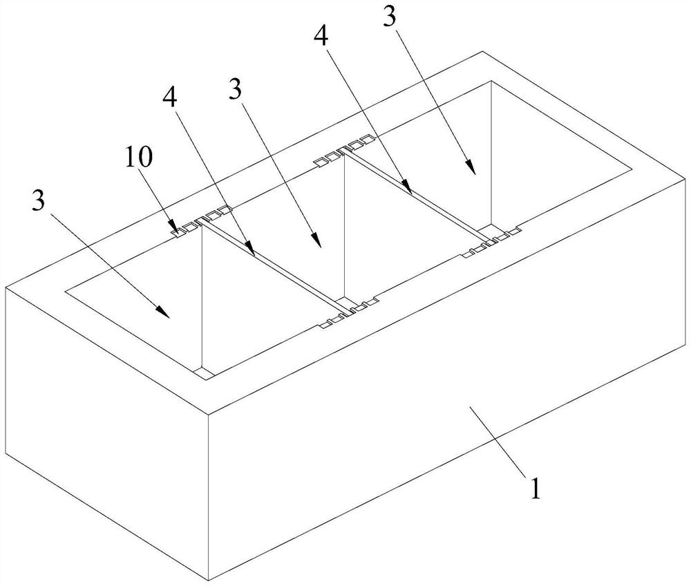
[0031] A transformer with high stability provided by this embodiment, such as Figure 1 to Figure 2 , comprising a shell 1, a coil set 2 and several pins (not shown in the drawings) mounted on the shell 1, the coil set 2 is provided with a plurality, the shell 1 is provided with an inner cavity, and the coil set 2 are electrically connected to the pins, and multiple insulating and isolating components 4 are installed in the housing 1, and the multiple insulating and isolating components 4 are detachably mounted on the housing 1, and the multiple insulating and isolating components 4 will T...


PUM


Abstract

The invention relates to the technical field of transformers, in particular to a high-stability transformer which comprises a shell, a coil assembly and a plurality of pins arranged on the shell, the shell is provided with an inner cavity, the coil assembly is electrically connected with the pins, a plurality of insulation isolation assemblies are arranged in the shell and detachably arranged on the shell, and the insulation isolation assemblies are electrically connected with the pins. An inner cavity of the shell is isolated into a plurality of accommodating cavities by the plurality of insulating isolation assemblies, and the plurality of accommodating cavities are respectively used for mounting the plurality of coil groups; the insulation isolation assembly comprises a plurality of insulation layers, the insulation layers are made of insulation colloid and are in a soft state, and the adjacent insulation layers are bonded. According to the transformer with the high stability, the detachable insulation isolation assembly is arranged to isolate the coil assembly, disassembly and assembly are convenient, the flexibility is high, the insulation layer is arranged to be in a soft state, when collision occurs, the insulation isolation assembly is not prone to being damaged, the isolation effect on the coil assembly is not prone to being affected, and the stability of the transformer is improved.

Description

technical field [0001] The invention relates to the technical field of transformers, in particular to a transformer with high stability. Background technique [0002] The network transformers on the market generally directly fix multiple coil groups directly into the casing, and there is no separation process between the coil groups, so the problem of creepage distance between adjacent coil groups is prone to occur. As the size of the network transformer is getting smaller and smaller, and the function requirements of the network transformer are getting higher and higher, the electronic components in the insulating shell are more and more, resulting in the magnetic ring coil components of the coil group in the process of producing the network transformer. The covered wire of the network transformer may be damaged, which leads to the momentary high voltage generated on the coil group of the network transformer may break through the insulation layer of the enameled wire and co...

Claims


Application Information

Patent Timeline
Patent Type & Authority Applications(China)
IPC IPC(8): H01F27/02H01F27/32
CPCH01F27/022H01F27/324
Inventor 杨逢春
Owner 赣州讯康电子科技有限公司
Why Eureka
Try Eureka