
Speed regulator

A technology of speed governor and speed regulating device, which is applied in the direction of electric brake/clutch, permanent magnet clutch/brake, asynchronous induction clutch/brake, etc., which can solve the problem of large torque decline trend and narrow speed regulation range of the governor , Can not be well adapted to fan load and other issues, to achieve the effect of increasing the speed regulation range

Active Publication Date: 2022-05-10
GUANGDONG UNIV OF TECH
View PDF4 Cites 0 Cited by
  • Summary
  • Abstract
  • Description
  • Claims
  • Application Information

AI Technical Summary

Problems solved by technology

[0003] As a magnetic transmission device, the permanent magnet governor can transmit torque between the motor and the load without contact, which eliminates the mechanical vibration caused by the mechanical contact between the motor and the load, and also has functions such as soft start and overload protection. It has been well applied in many industrial fields, such as fans, pumps, conveyors, etc. At present, the torque peak value of the speed-torque characteristic curve of the high-power governor is very high, but after the torque reaches the peak value, the With the increase of slip, the torque decline trend is relatively large, which cannot be well adapted to fan loads, which will cause the speed range of the governor to be too narrow, and the function of the governor cannot meet the actual needs

Method used


Image

  • Speed regulator
  • Speed regulator
  • Speed regulator

Examples


Embodiment Construction

[0024] This part will describe the specific embodiment of the present invention in detail, and the preferred embodiment of the present invention is shown in the accompanying drawings. Each technical feature and overall technical solution of the invention, but it should not be understood as a limitation on the protection scope of the present invention.

[0025] In the present invention, if there is a description of directions (up, down, left, right, front and back), it is only for the convenience of describing the technical solution of the present invention, rather than indicating or implying that the referred technical features must have specific Orientation, construction and operation in a particular orientation, therefore should not be construed as limiting the invention.

[0026] In the present invention, "several" means one or more, "multiple" means more than two, "greater than", "less than", "exceeding", etc. are understood as excluding the original number; "above", "belo...


PUM


Abstract

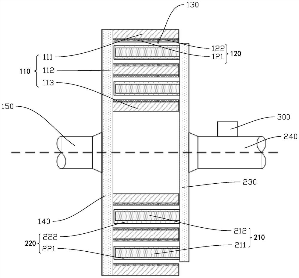
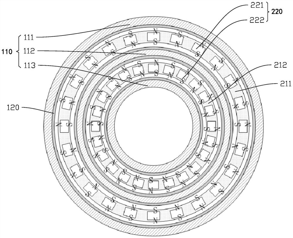
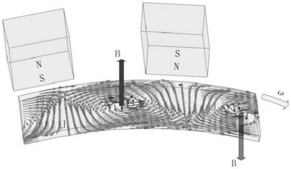
A speed regulator disclosed by the present invention comprises a first rotating mechanism and a second rotating mechanism, the first rotating mechanism comprises a first cylinder, the first cylinder is provided with a conductor, the second rotating mechanism comprises a second cylinder coaxially arranged with the first cylinder, and the second cylinder is provided with a plurality of permanent magnets at intervals. The permanent magnets surround the second cylinder in the circumferential direction, the magnetic pole directions of the adjacent permanent magnets are opposite, the first cylinder and the second cylinder are kept in a non-contact coupling state, and the conductor generates eddy current and forms an induced magnetic field. The first rotating mechanism drives the second rotating mechanism to rotate through interaction of an induced magnetic field and a permanent magnet magnetic field, the rotating speed of the second rotating mechanism is changed by changing the coupling area of the first cylinder and the second cylinder, and an insulating part is arranged on the conductor. The conductor is divided into a plurality of conductors along the axial direction by the insulating parts, and the speed regulator is large in speed regulation range and is more suitable for loads such as fans.

Description

technical field [0001] The invention is used in the field of mechanical transmission, and in particular relates to a speed governor. Background technique [0002] The permanent magnet speed governor generates relative motion between the permanent magnet and the conductor, so that the conductor generates eddy current in the transformed magnetic field, generates a repulsive magnetic field and interacts with the original magnetic field to make the rotor rotate. As the coupling area decreases, the speed of the driven-end rotor also decreases. [0003] As a magnetic transmission device, the permanent magnet governor can transmit torque between the motor and the load without contact, which eliminates the mechanical vibration caused by the mechanical contact between the motor and the load, and also has functions such as soft start and overload protection. It has been well applied in many industrial fields, such as fans, pumps, conveyors, etc. At present, the torque peak value of t...

Claims


Application Information

Patent Timeline
Patent Type & Authority Applications(China)
IPC IPC(8): H02K49/04H02K49/10
CPCH02K49/043H02K49/106
Inventor 赵韦人吴鹏向
Owner GUANGDONG UNIV OF TECH
Learn More