Multifunctional material taking device for pathology department

A multi-functional and pathological technology, applied in application, surgical equipment, medical science, etc., can solve problems such as pollution and touch, and achieve the effect of avoiding pollution, avoiding sharp-edged hand injuries, and simple methods

Inactive Publication Date: 2022-05-13
GUILIN MEDICAL UNIVERSITY
View PDF0 Cites 0 Cited by
  • Summary
  • Abstract
  • Description
  • Claims
  • Application Information

AI Technical Summary

Problems solved by technology

[0002] The pathology department needs to use a variety of instruments for pathological tests; currently, the instruments are placed in a unified box and box for direct access. This method is easy to touch the tip of the instrument, and the hand will touch the unused equipment, causing pollution; after use, it is necessary to transfer the equipment for cleaning. For this reason, a multifunctional material collection device for pathology is proposed

Method used


Image

  • Multifunctional material taking device for pathology department
  • Multifunctional material taking device for pathology department
  • Multifunctional material taking device for pathology department

Examples


Embodiment 1

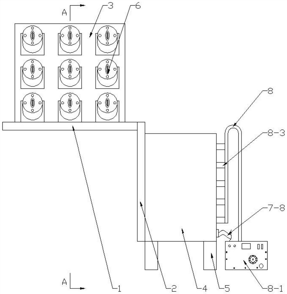
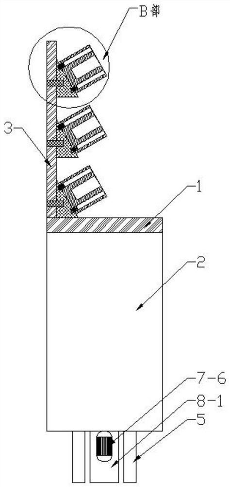
[0055] In Embodiment 1, the No. 1 platform 1 is placed on the working console, the No. 2 platform 2 is close to the side wall of the console, and the equipment is placed on the fixing mechanism 6 on the support plate 3; after use, the The instrument is placed in the cleaning box 4 , cleaned by the cleaning mechanism 7 , dried by the drying mechanism 8 , and taken out and put back into the fixing mechanism 6 .

Embodiment 2

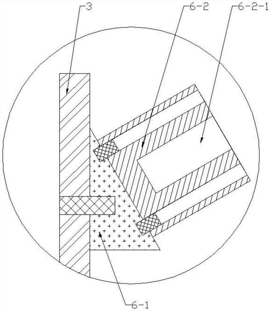
[0057] see Figure 1-Figure 3 , on the basis of Embodiment 1, the fixing mechanism 6 includes:

[0058] The triangular block 6-1, the triangular block 6-1 is fixed on the support plate 3 by bolts, and the front side wall of the triangular block 6-1 is arranged inclined from back to front from top to bottom;

[0059] Silica gel column 6-2, the silica gel column 6-2 is fixed on the front side wall of the triangular block 6-1 by bolts, and the front side of the silica gel column 6-2 is provided with a slot 6-2-1;

[0060] The marking layer 6-3, the marking layer 6-3 is arranged on the outside of the slot 6-2-1 of the front side wall of the silica gel column 6-2;

[0061] Using this embodiment, according to the indication of the marking layer 6-3, insert the instrument into the slot 6-2-1 of the corresponding silica gel column 6-2, so that the instrument is fixed in the silica gel column 6-2; replace the silica gel column 6 -2, unscrew the bolts in the triangular block 6-1 and t...

Embodiment 3

[0063] see figure 1 , Figure 4-Figure 8 , on the basis of Example 1, the cleaning mechanism 7 includes:

[0064] Net frame 7-1, the quantity of described net frame 7-1 is several, and is respectively arranged in the cleaning box 4 from top to bottom, and net frame 7-1 is the front side open type structure, two adjacent up and down A screen frame 7-1 is welded and fixed;

[0065] Ultrasonic generator 7-2, described ultrasonic generator 7-2 is arranged on the inner base plate of cleaning box 4, and ultrasonic generator 7-2 is connected with external power supply, and the specific use model of ultrasonic generator 7-2 is according to actual use It is required to purchase, install and use directly from the market;

[0066] The limit rod 7-3, the limit rod 7-3 is fixed on the left side of the inner bottom plate of the cleaning box 4 by bolts;

[0067] The limit ring 7-4, the limit ring 7-4 is movably sleeved on the limit rod 7-3, and the right side of the ring wall of the limit ...


PUM


Abstract

The invention discloses a multifunctional material taking device for the pathology department, and relates to the technical field of medical instrument assistance. The supporting legs are fixed to the four corners of the bottom of the cleaning box. The fixing mechanisms are distributed on the front side wall of the supporting plate in a matrix mode. The cleaning mechanism is arranged in the cleaning box; the drying mechanism is arranged on the right side of the cleaning box and connected with the cleaning box. The instrument fixing mode is simple, hands are prevented from being hurt by sharp ends, unused instruments cannot be touched, pollution is avoided, and the instruments are convenient to take. During use, instruments can be placed in the net frame, so that the instruments can be cleaned in time after use and do not need to be transferred.

Description

technical field [0001] The invention relates to the field of medical device auxiliary technology, in particular to a multifunctional material-taking device for pathology departments. Background technique [0002] The pathology department needs to use a variety of instruments for pathological tests; currently, the instruments are placed in a unified box and box for direct access. This method is easy to touch the tip of the instrument, and the hand will touch the unused Equipment, causing pollution; after use, it is necessary to transfer the equipment for cleaning. For this reason, a multifunctional device for obtaining materials for pathology is now proposed. Contents of the invention [0003] The purpose of the present invention is to address the defects and insufficiencies of the prior art, and propose a multifunctional device for obtaining materials for pathology. And it is easy to take; the instrument can be placed in the frame when in use, which is convenient for clea...

Claims


Application Information

Patent Timeline
Patent Type & Authority Applications(China)
IPC IPC(8): A61B50/24A61B90/70B08B3/12F26B21/00
CPCA61B50/24A61B90/70B08B3/12F26B21/001F26B21/004
Inventor 郑锦花孙江滨郑翔魏亚敏鲁蓝忆
Owner GUILIN MEDICAL UNIVERSITY
Why Eureka
Try Eureka