Equipment device of automobile metal plate stamping die
A technology of stamping dies and equipment devices, applied in metal processing equipment, feeding devices, positioning devices, etc., can solve problems such as affecting the processing quality of sheet metal parts, damaging the surface of sheet metal parts, improving labor intensity, etc., and achieving easy storage and regularity. , The effect of protecting sheet metal and improving safety
- Summary
- Abstract
- Description
- Claims
- Application Information
AI Technical Summary
Problems solved by technology
Method used
Image
Examples
Embodiment 1
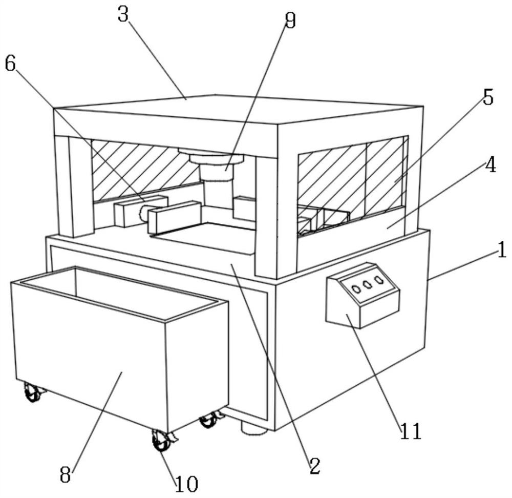
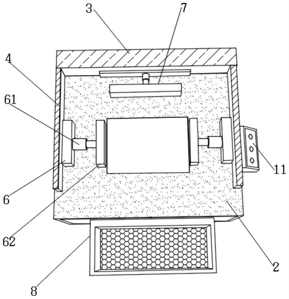
[0038] Such as Figure 1-7 As shown, the present invention provides a kind of equipment device of automobile sheet metal stamping die, comprises sheet metal stamping equipment 1, and the upper part of sheet metal stamping equipment 1 is provided with workbench 2, and the upper part of workbench 2 is provided with sheet metal fixing assembly 6 , the rear side away from the sheet metal fixing assembly 6 is provided with a blanking cleaning assembly 7, the front of the sheet metal stamping equipment 1 is provided with a sheet metal storage box 8, the inside of the protective cover 3 is provided with a stamping element 9, and the sheet metal fixing assembly 6 includes The first electric telescopic link 61, the right end of the first electric telescopic link 61 is provided with stabilizing splint 62, and blanking cleaning assembly 7 comprises blanking push plate 74, and the bottom of blanking push plate 74 is provided with cleaning brush 75.
[0039] When in use, place the sheet me...
Embodiment 2
[0041] Such as Figure 1-7 As shown, on the basis of Embodiment 1, the present invention provides a technical solution: preferably, the upper and lower ends of the stabilizing splint 62 are provided with a movable shaft 63, and the outer part of the movable shaft 63 is movable with an arc-shaped limiting plate 64, The outside of the stabilizing splint 62 is fixedly equipped with an elastic extruding plate 65, and the inner side of the elastic extruding plate 65 is fixedly connected with a protective elastic block 66, and the left side of the protective elastic block 66 is fixedly installed with a partition plate 67. A first buffer block 68 is fixedly installed on the left side.
[0042] The left side of the first buffer block 68 is fixedly equipped with an anti-pressure ball 69, and the left side of the anti-pressure ball 69 is fixedly equipped with a second buffer block 70, and the right side of the anti-pressure ball 69 and the left side of the dividing plate 67 pass through...
Embodiment 3
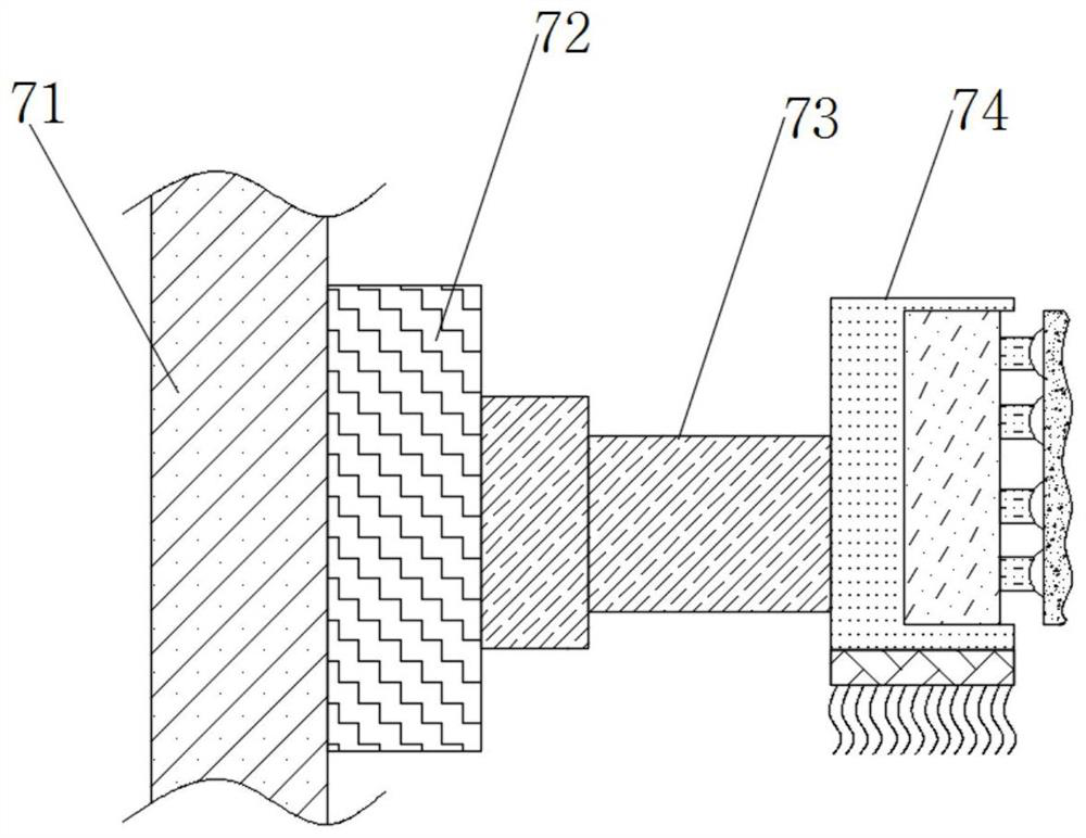
[0045] Such as Figure 1-7 As shown, on the basis of Embodiment 1, the present invention provides a technical solution: preferably, the left end of the blanking push plate 74 is provided with a second electric telescopic rod 73, and the left side of the second electric telescopic rod 73 is provided with a mounting Seat 72, the left side of mounting seat 72 is fixedly installed with mounting plate 71.
[0046] The inside of blanking push plate 74 is fixedly installed with installation sleeve 76, and the inwall of installation sleeve 76 is fixedly installed with telescopic spring 77, and the right end of telescopic spring 77 is fixedly installed with connecting rod 78.
[0047] The right end of connecting rod 78 is fixedly installed with hemispherical fixed block 79, and the right end of hemispherical fixed block 79 is fixedly installed with elastic outer plate 80, and the right end of telescopic spring 77 is fixedly connected with the left end of hemispherical fixed block 79 by...
PUM
 Abstract
Description
Claims
Application Information
 - R&D
- Intellectual Property
- Life Sciences
- Materials
- Tech Scout
- Unparalleled Data Quality
- Higher Quality Content
- 60% Fewer Hallucinations
Browse by: Latest US Patents, China's latest patents, Technical Efficacy Thesaurus, Application Domain, Technology Topic, Popular Technical Reports.
© 2025 PatSnap. All rights reserved.Legal|Privacy policy|Modern Slavery Act Transparency Statement|Sitemap|About US| Contact US: help@patsnap.com


