Tire vulcanization production line
A tire vulcanization and production line technology, applied in tires, household appliances, other household appliances, etc., can solve the problem of low material filling efficiency and achieve the effect of improving filling efficiency
Pending Publication Date: 2022-05-13
青岛科捷机器人有限公司
0 Cites 0 Cited by
AI-Extracted Technical Summary
Problems solved by technology
[0004] However, when using a vertical vulcanizing machine for production at present, due to the need to continuously install tire mo...
View moreMethod used
Referring to Fig. 1 and Fig. 2, in order to facilitate the staff to complete the process of installing the tire mold on the tooling plate 3, a lift is arranged between the filler conveying device 24, the feeding conveying device 21 and the return conveying device 23. Frame 26, a lifting platform 261 is horizontally arranged in the lifting frame 26, and the lifting height of the lifting platform 261 is set according to the height of the operator, so that the operator can complete placing the tire mold on the tooling plate 3 without bending over This process saves manpower. The driving element of the lifting platform 261 can be a lifting cylinder, the lifting cylinder is vertically arranged, and the cylinder body of the lifting cylinder is fixed on the lifting frame 26, and the telescopic rod of the lifting cylinder is fixed on the lifting platform 261.
With reference to Fig. 3 and Fig. 4, the downside of horizontal movable arm 73 slides and is connected with slide table 74 along its lengthwise direction, horizontal movable arm 73 is also provided with the drive mechanism that can drive slide table 74 to move, and drive mechanism includes setting The pulleys 741 at both ends of the horizontal movable arm 73 in the length direction, the transmission belt 742 outside the pulleys 741 at both ends of the horizontal movable arm 73 along the horizontal movable arm 73, and the belt that is fixed on the horizontal movable arm 73 and can drive the belt pulley 741 to rotate The fourth servo motor 743 . The slide table 74 is fixed on the transmission belt 742. When the fourth servo motor 743 drives the pulley 741 to rotate, the transmission belt 742 can be driven to rotate, thereby dragging the slide table 74 to slide along the length direction of the horizontal movable arm...
View moreAbstract
The invention relates to the field of vulcanization production lines, in particular to a tire vulcanization production line which comprises a rotary conveying system which is horizontally and annularly arranged on the filler side of a vertical vulcanizing machine, and a plurality of tool plates are arranged on the rotary conveying system and used for placing forming dies; the tool plates can be driven by the rotary conveying system to move annularly. The filling system is movably arranged above the rotary conveying system along the filling direction perpendicular to the vertical vulcanizing machine and is used for conveying the moulding bed on the tooling plate to the vertical vulcanizing machine; and the material taking system is movably arranged above the rotary conveying system in the direction perpendicular to the filling direction of the vertical vulcanizing machine, and is used for taking out the materials in the vulcanizing machine and placing the materials in the discharging conveying system. The device has the effect of improving the material filling efficiency.
Application Domain
Technology Topic
Image
Examples
- Experimental program(1)
Example Embodiment
[0067] Attached to the following Figure 1-7 This application will be described in further detail.
[0068] The embodiment of the present application discloses a tire vulcanization production line, which is mainly used in the field of tire vulcanization production.
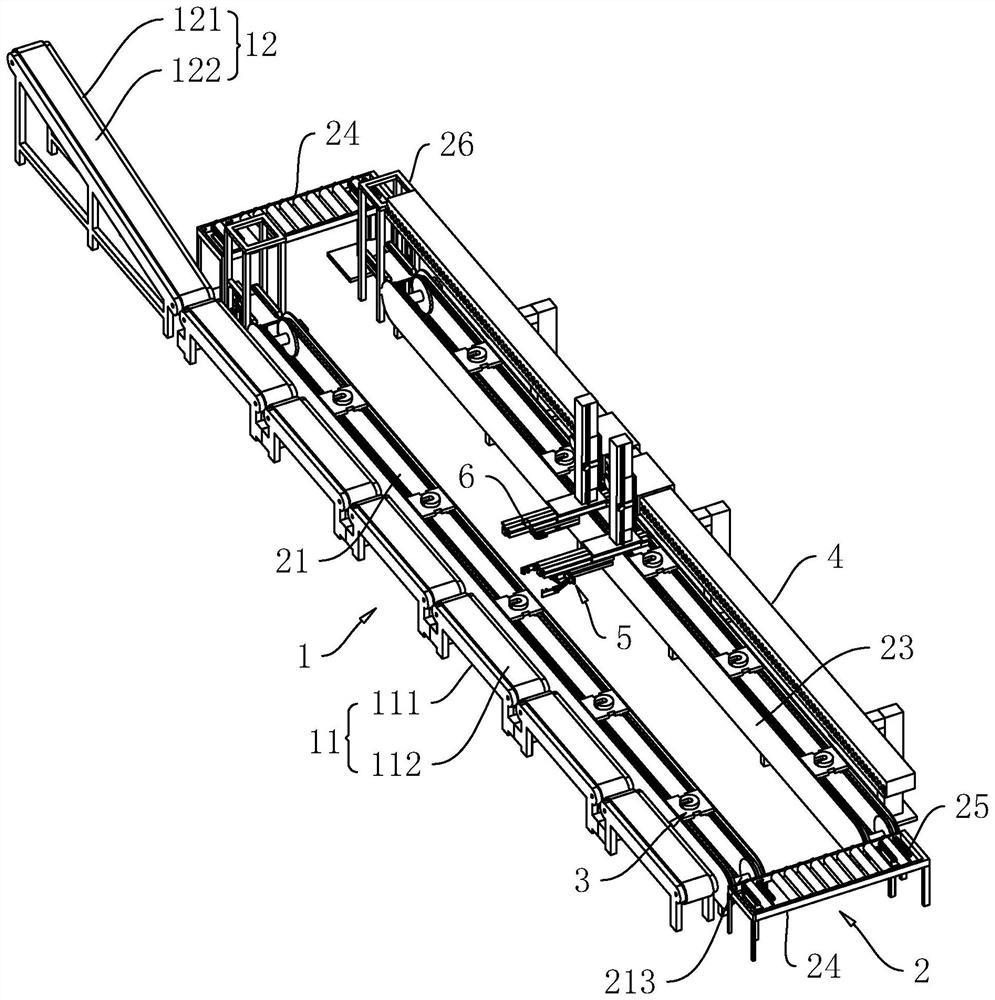
[0069] refer to figure 1 , a tire vulcanization production line, including a discharge conveying system 1, a rotary conveying system 2 and a mobile clamping unit.
[0070] When setting up the production line, firstly, multiple vertical vulcanizers are arranged along the same straight line, and the filler sides of the multiple vertical vulcanizers are all facing the same side. Then, the discharge conveying system 1 is arranged horizontally on the discharge side of the multiple vertical vulcanizers, and the conveying direction of the discharge conveying system 1 is the same as the placement direction of the multiple vertical vulcanizers. The machine-vulcanized tire can be directly placed in the discharge conveying system 1 to be conveyed out after being taken out.
[0071] The rotary conveying system 2 is arranged on the side of the discharging conveying system 1 away from the vertical vulcanizing machine, which is used to carry the tire mold and realize the rotary conveying and feeding of the tire mold. It is used to realize the delivery of the tire mold on the rotary conveying system 2 to each vertical vulcanizing machine, and to realize the realization of taking out the tire mold and the tire mold that have been vulcanized in the vulcanizing machine and then sending them to the discharging conveying system 1 to complete the discharging.
[0072] The detailed structures of the discharge conveying system 1 , the rotary conveying system 2 and the mobile gripping unit will be described in detail below.
[0073] refer to figure 1 , the discharge conveying system 1 mainly includes several horizontal conveying modules 11 and an inclined conveying module 12 spliced together. The plurality of horizontal conveying modules 11 are arranged end to end along their length direction, and the conveying directions of the plurality of horizontal conveying modules 11 are the same. one end, and the conveying direction of the inclined conveying module 12 is the same as the conveying direction of the horizontal conveying module 11 .
[0074] refer to figure 1 Each of the horizontal conveying modules 11 includes a first frame body 111. The first frame body 111 is provided with a horizontal conveying belt 112 with the same length direction and a first driving element, such as a driving motor, that drives the horizontal conveying belt 112 to rotate continuously. The inclined conveying module 12 includes a second frame body 121 inclined on the upper side, and the lower end of the second frame body 112 is close to the first frame body 111 , and the upper side of the second frame body 121 is disposed in the same direction as the inclination direction of the upper side. The inclined conveyor belt 122 and a second driving element that drives the inclined conveyor belt 122 to rotate continuously, such as a drive motor.
[0075] refer to figure 1 , the lower end of the inclined conveyor belt 122 is connected to the horizontal conveyor belt 112, and the height of the horizontal conveyor belt 112 is not higher than the lowest side of the filler side of the vertical vulcanizer, and the higher side of the inclined conveyor belt 122 according to the staff The height of the machine is reasonably set, so that the staff can easily remove the tire mold sent by the inclined conveyor belt without bending over.
[0076] refer to figure 1 , When the tire vulcanization is completed, the tire integrated with the tire mold after the vulcanization in each vertical vulcanizing machine can be taken out by moving the clamping unit, and then placed on the upper side of the horizontal conveying module 11 in the direction of the filling port of each vulcanizing machine, and then, The tires are sequentially conveyed to the inclined conveying module 12 through a plurality of horizontal conveying modules 11, and the inclined conveying module 12 then conveys the tires to a position where the workers can manually operate, and the vulcanized tires can be separated from the tire mold.
[0077] refer to figure 1 and figure 2 The rotary conveying system 2 mainly includes a feeding conveying device 21 , a reversing conveying device 22 , a returning conveying device 23 and a filling conveying device 24 which are connected end to end in a ring shape. The return conveying device 23 is also provided with a number of rectangular tooling plates 3, and the plurality of tooling plates 3 can be continuously rotated through the feeding conveying device 21, the reversing conveying device 22, the returning conveying device 23 and the filling conveying device 24. .
[0078] refer to figure 1 and figure 2 The upper side of the tooling plate 3 is used to place the tire mold. In order to facilitate the positioning of the tire mold, a positioning plate 31 is integrally formed on the tooling plate 3, and a positioning gap 32 is provided on one side of the peripheral surface of the positioning plate 31. When placing the tire mold, the ring-shaped tire mold with the air nozzle can be directly set on the positioning plate 31, and the air nozzle of the tire mold can be inserted into the positioning gap 32, so as to realize the connection between the tire mold and the tooling plate 3. The relative position is limited so that when the tire mold is conveyed on the tooling plate 3, it will not move relative to the tooling plate 3, so as to ensure the accurate feeding of the subsequent tire mold. The feeding conveying device 21 and the returning conveying device 23 are parallel to each other and are arranged along the length direction of the discharging conveying system 1, and the conveying direction of the feeding conveying system is opposite to that of the outgoing conveying system, while the conveying direction of the rotary conveying system 2 The conveying direction is the same as that of the discharge conveying system 1. In order to ensure the convenient feeding of each vertical vulcanizer, the length of the feeding conveying system and the discharging conveying system 1 should not be less than the arrangement length of multiple vertical vulcanizers.
[0079] refer to figure 1 and figure 2, the feeding conveying device 21 and the returning conveying device 23 both include two horizontally arranged first fixing frames 211, the length direction of the first fixing frame 211 is the same as the conveying direction of the discharging conveying system 1, and the two first fixing frames 211 Each of the two sides is sleeved with a conveying bar 212 with the same length direction, and the height of the upper side of the conveying bar 212 is lower than the height of the first fixing frame 211 . In order to ensure the transportation and positioning of the tooling plate 3, it should be set on the upper side of the conveying bar 212 when the tooling plate 3 is placed between the two first fixings, and the distance between the two conveying bars 212 should be able to ensure that the upper side of the two conveying bars 212 Abutting on the tooling plate 3, and the distance between the two first fixing brackets 211 should be kept so as to be able to abut on the far side of the tooling plate 3, so as to ensure that the tooling plate 3 will not shift during the conveying process.
[0080] refer to figure 1 and figure 2 A driving roller 213 is rotatably connected between the ends of the two first fixing frames 211, the axis direction of the driving roller 213 is perpendicular to the length direction of the conveying bar 212, and the same ends of the two conveying bars 212 are respectively sleeved on the same driving roller 213 both ends of . One end of the two first fixing frames 211 corresponding to a driving roller 213 is provided with a third driving element, and the third driving element can drive the driving roller 213 to rotate, such as a driving motor. During operation, the third driving element drives a driving roller 213 to rotate, which can drive the two conveying bars 212 of the two first fixing frames 211 to rotate synchronously.
[0081] refer to figure 1 and figure 2 , the reversing conveying device 22 is arranged at one end of the feeding conveying device 21 and the returning conveying device 23, the filling conveying device 24 is arranged at the other end of the feeding conveying device 21 and the returning conveying device 23, and the reversing conveying device 22 and the filler The length direction of the conveying device 24 is perpendicular to the length direction of the feeding conveying device 21 and the returning conveying device 23 , and the reversing conveying device 22 and the filling conveying device 24 are both used to connect the feeding conveying device 21 and the returning conveying device 23 .
[0082] refer to figure 1 and figure 2 The conveying direction of the reversing conveying device 22 is from one end of the feeding conveying device 21 to one end of the returning conveying device 23, and the conveying direction of the filling conveying device 24 is from one end of the returning conveying device 23 to one end of the feeding conveying device 21. delivery. Therefore, the rotary conveying system 2 is realized by the feeding conveying device 21 , the reversing conveying device 22 , the returning conveying device 23 and the filling conveying device 24 .
[0083] refer to figure 1 and figure 2 , the reversing conveying device 22 and the filling conveying device 24 both include a second fixing frame 221, the length direction of the second fixing frame 221 is perpendicular to the length direction of the discharging conveying system 1, and a plurality of electric motors are arranged on the second fixing frame 221. For the rollers 222 , the axis direction of each electric roller 222 is perpendicular to the length direction of the second fixing frame 221 , and the plurality of electric rollers 222 are arranged along the length direction of the second fixing frame 221 . During operation, the plurality of electric rollers 222 cooperate with each other, so that the conveying of the tooling plate 3 can be realized.
[0084] refer to figure 1 and figure 2 The position of the reversing conveying device 22 and the filling conveying device 24 near the ends of the feeding conveying device 21 and the returning conveying device 23 is provided with a lifting conveying device 25. The lifting driving element of 251 can be a lifting cylinder, the lifting cylinder is vertically arranged, the cylinder body of the lifting cylinder is fixed to the second fixing frame 221 , and the telescopic rod of the lifting cylinder is fixed to the lifting plate 251 .
[0085] refer to figure 1 and figure 2 , the lift plates 251 are provided with two parallel reversing conveyor belts 252 and a fourth driving element, such as a driving motor, that drives the two reversing conveyor belts 252 to rotate synchronously. The length direction of the reversing conveyor belts 252 is the same as the axis direction of the electric rollers 222, and the reversing conveyor belts 252 are arranged between the adjacent electric rollers 222, so that when the lifting plate 251 drives the two conveyor belts to rise, it can The two motorized rollers 222 are raised between the adjacent motorized rollers 222 to realize docking with the feeding conveying device 21 or the returning conveying device 23 .
[0086] refer to figure 1 and figure 2 , in order to facilitate the reversing conveyance of the tooling plate 3 by the lifting conveying device 25, the conveying direction of the reversing conveyor belts at both ends of the feeding conveying device 21 should be the same as the conveying direction of the feeding conveying device 21; The conveying direction of the lift conveying devices 25 at both ends should be the same as the conveying direction of the return conveying device 23 .
[0087] refer to figure 1 and figure 2 , the upper side of the electric roller 222 of the reversing conveying device 22 is lower than the upper side of the conveying bar 212, so that when the loading conveying device 21 drives the tooling plate 3 to be conveyed to the position of the reversing conveying device 22, the lifting conveying device 25 The lifting plate 251 rises, driving the upper side of the reversing conveyor belt 252 to protrude from the upper side of the electric roller 222 and docking with the feeding conveying device 21, so that the tooling plate 3 is directly transported to the upper side of the reversing conveyor belt, and then the lifting plate 251 Descend until the upper side of the reversing conveyor belt 252 is lower than the upper side of the electric roller 222, the tooling plate 3 will fall to the upper side of the electric roller 222, and then the tooling plate 3 will be directly conveyed to the return material through the electric roller 222 One end of the conveying device 23 is driven by the lifting plate 251 at the other end of the reversing conveying device 22 to drive the reversing conveyor belt to lift up the tooling plate 3, and the tooling plate 3 is sent to the return conveyor belt through the reversing conveyor belt 252, that is, The reversing conveyance of the tooling plate 3 between the feeding conveying device 21 , the reversing conveying device 22 and the returning conveying device 23 can be completed.
[0088] refer to figure 1 and figure 2 , in order to facilitate the staff to complete the process of installing the tire mold on the tooling plate 3, a lifting frame 26 is provided between the filler conveying device 24, the feeding conveying device 21 and the returning conveying device 23, and the lifting frame 26 is horizontally arranged. There is a lift table 261, the lift height of the lift table 261 is set according to the height of the operator, so that the operator can complete the process of placing the tire mold on the tooling plate 3 without bending over, saving manpower. The driving element of the lift table 261 can be a lift cylinder, the lift cylinder is vertically arranged, the cylinder body of the lift cylinder is fixed to the lift frame 26 , and the telescopic rod of the lift cylinder is fixed to the lift table 261 .
[0089] refer to figure 1 and figure 2 , the upper side of the lifting platform 261 is provided with a transposition conveyor belt 262 and a fifth driving element for driving the transposition conveyor belt 262 to rotate, such as a drive motor. The length direction of the transposition conveyor belt 262 is the same as the length direction of the feeding conveyor 21 and the return conveyor 23, and the conveying direction of the transposition conveyor belt 262 close to the return conveyor 23 is the same as that of the return conveyor 23. ; The conveying direction of the filler conveying close to the feeding conveying device 21 is the same as the conveying direction of the feeding conveying device 21 . With the lifting and lowering of the lifting platform 261 , the transposition conveyor belt 262 can be connected to the feeding and conveying device 21 and the filler conveying device 24 . Therefore, after the tooling plate 3 is transported to the transposition conveyor belt 262 of the lifting frame 26, the tooling plate 3 can be lifted by the lifting of the lifting plate 251, so that the tooling plate 3 can be sent to the worker without bending over to place the tire mold. on the tooling board 3.
[0090] refer to figure 1 and figure 2 , in order to facilitate the direct conveyance of the workpieces on the lift plate 251 to the filler conveying device 24, the height of the upper side of the filler conveying device 24 can be set to be flush with the height of the transposition conveyor belt 262 after the lift plate 251 rises, so as to complete the lift plate 251 After the upper tire mold is placed, it can directly cooperate with the lifting and conveying device 25 at one end of the filler conveying device 24 through the transposition conveyor belt 262, and directly send the tooling plate 3 with the tire mold to the lifting and conveying device 25 at one end of the filler conveying device 24. , and then through the rotation of the electric roller 222 on the filling conveyor belt, the tooling plate 3 equipped with the tire mold is conveyed in the direction of the feeding conveying device 21, and then the lifting conveying device 25 at the other end of the filling conveying device 24 and the other lifting frame 26 The upper lifting table cooperates, and the tooling plate 3 with the tire mold is transported to the transposition conveyor belt 262 of the lifting table 261, and the transposition conveyor belt 262 on the lifting table 261 is transported to the feeding conveying device 21 for filling. The device sends the tire mold to the vertical vulcanizing machine, and the tooling plate 3 after taking the tire mold continues to be cyclically loaded.
[0091] refer to image 3 , the mobile clamping unit includes a support device 4 and a filling system 5 and a reclaiming system 6 arranged on the support device 4. The filling device is used to realize the removal of the tire mold from the tooling plate 3 at the feeding and conveying device 21, and It is sent to the vertical vulcanizer to complete the filling process; the reclaiming device is used to take out the tires and tire molds vulcanized by the vertical vulcanizer and send them to the discharge conveying system 1 to complete the reclaiming process.
[0092] refer to image 3 , the support device 4 includes a horizontal beam 41 , the beam 41 and the feeding conveying device 21 are arranged in the longitudinal direction, and the beam 41 is located above the feeding conveying device 21 and the returning conveying device 23 . The lower side of the beam 41 is fixed with a plurality of columns 42 for supporting the beam 41. The position of the columns 42 can be adjusted according to the overall layout of the production line, so as to support the beam 41 without hindering the operation of other components.
[0093] refer to image 3 and Figure 4 , the filling system 5 and the reclaiming system 6 both include a drive unit 7 , and the drive unit 7 includes a horizontal movable frame 71 , a vertical movable arm 72 , and a horizontal movable arm 73 . The horizontal movable frame 71 slides on the beam 41 along the length direction of the beam 41 , and the first rack 411 is fixed on the beam 41 along its length direction, and the first servo motor 711 is fixed on the horizontal movable frame 71 , and the first servo motor 711 The output shaft is fixed with a first gear 712, which is meshed with the first rack 411. During operation, the first servo motor 711 drives the first gear 712 to rotate, and the first gear 712 meshes with the first rack 411 for transmission. , the horizontal movable frame 71 can be driven to slide along the length direction of the beam 41 .
[0094] refer to image 3 and Figure 4 , the vertical movable arm 72 is vertically slidingly connected to the side of the horizontal movable frame 71 close to the vertical vulcanizing machine, the vertical movable arm 72 is vertically fixed with a second rack 721, and the horizontal movable frame 71 is fixed with a second rack 721. The servo motor 713 and the output shaft of the second servo motor 713 are fixed to the second gear 714 , and the second gear 714 is engaged with the second rack 721 . During operation, the second servo motor 713 drives the second gear 714 to rotate, and the vertical movement of the vertical movable arm 72 can be realized through the meshing transmission between the second gear 714 and the second rack 721 .
[0095] refer to image 3 and Figure 4 , the lower side of the vertical movable arm 72 is also fixed with a horizontally arranged guide rail frame 723, the horizontal movable arm 73 slides horizontally on the guide rail frame 723, and the length direction of the horizontal movable arm 73 and the length direction of the guide rail frame 723 are both perpendicular to In the length direction of the beam 41, the horizontal movable arm 73 slides along the length direction of the guide rail frame 723, and can move toward or away from the vertical vulcanizing machine. A third servo motor 724 is fixed on the beam 723 , a third gear 725 is fixed on the output shaft of the third servo motor 724 , and the third gear 725 is engaged with the third rack 731 . During operation, the third servo motor 724 drives the third gear 725 to rotate, and through the transmission of the third gear 725 and the third rack 731 , the horizontal movable arm 73 can be driven to move along its length direction.
[0096] refer to image 3 and Figure 4, the lower side of the horizontal movable arm 73 is slidingly connected with the sliding table 74 along its length direction, and the horizontal movable arm 73 is also provided with a driving mechanism capable of driving the sliding table 74 to move. The pulley 741 , the transmission belt 742 on the outside of the pulleys 741 at both ends of the horizontal movable arm 73 are sleeved along the horizontal movable arm 73 , and the fourth servo motor 743 fixed on the horizontal movable arm 73 and capable of driving the pulley 741 to rotate. The sliding table 74 is fixed on the transmission belt 742. When the fourth servo motor 743 drives the pulley 741 to rotate, it can drive the transmission belt 742 to rotate, thereby dragging the sliding table 74 to slide along the length direction of the horizontal movable arm 73. In order to avoid the transmission belt 742 and the belt The pulley 741 slips to improve the transmission accuracy, the transmission belt 742 can be a synchronous belt, and the pulley 741 can be a synchronous pulley 741, so as to ensure the sliding stability of the sliding table 74 .
[0097] refer to Figure 5 , the filling system 5 also includes a filling device fixed on the lower side of the sliding table 74. The filling device includes a horizontally arranged horizontal frame 51. The direction is perpendicular to the length direction of the horizontal movable arm 73. Both ends of the length direction of the horizontal frame 51 are provided with a swing arm 52. The swing arm 52 is horizontally arranged on the side of the horizontal frame 51 close to the vertical vulcanizer. The length of the swing arm 52 The direction is perpendicular to the length direction of the horizontal frame 51 , one end of the swing arm 52 in the length direction is hinged to the horizontal frame 51 , and the other end of the swing arm 52 is connected with a clamping plate 53 that can swing with the swing arm 52 . The direction is the same as the longitudinal direction of the swing, and a first telescopic cylinder 54 is also fixed in the middle of the two horizontal frames 51 in the longitudinal direction. The telescopic rod faces the vertical vulcanizer, a connecting rod 55 is arranged between the telescopic rod of the first telescopic cylinder 54 and the two swing arms 52, one end of the connecting rod 55 is hinged to the swing arm 52, and the other end of the connecting rod 55 is hinged to the The telescopic rod of the telescopic cylinder.
[0098] refer to Figure 5 When the first telescopic cylinder 54 drives the telescopic rod to expand and contract, the two connecting rods 55 can drive the two swing arms 52 to swing toward or away from each other, thereby driving the two clamping plates 53 to realize the clamping or loosening process.
[0099] refer to Figure 5 In order to improve the stability of the clamping plate 53 when clamping the annular tire mold, clamping teeth 531 are fixed on the sides of the clamping plates 53 that are close to each other, and each clamping plate 53 is along the length of the clamping plate 53 Two clamping teeth 531 are arranged in a row, and the ends of the two clamping teeth 531 of the same clamping plate 53 away from the corresponding clamping plate 53 are inclined in a direction that they approach each other. The ends of the clamping teeth 531 are also provided with "V"-like clamping grooves 532 in the horizontal direction. Furthermore, when the two clamping plates 53 tend to move toward each other, the two clamping and cooperating clamping grooves 532 of each clamping plate 53 can adapt to the contour of the annular tire mold, thereby ensuring the clamping stability of the tire mold.
[0100] refer to Figure 5 In addition, in order to overcome the problem that the driving force of the telescopic cylinder is low, the swing arm 52 can be set as two mutually parallel swing rods 521, one end of the two swing rods 521 is hinged to the horizontal frame 51, and the two swing rods 521 The other end is hinged to the clamping plate 53 , and one end of each link 55 hinged to the swing arm 52 is hinged to the two links 55 at the same time. Therefore, the two pendulum rods 521 cooperate with the horizontal frame 51 and the clamping plate 53 to form a parallelogram-like mechanism, so as to improve the clamping force of the clamping plate 53 .
[0101] refer to Image 6 and Figure 7 , the reclaiming system 6 also includes a reclaiming device fixed on the sliding table 74, the material reclaiming device includes a receiving plate 61, and the receiving plate 61 is arranged on the side of the sliding table 74 close to the vertical vulcanization frame, in order to ensure that the receiving plate 61 can be inserted In the vertical vulcanizing machine, the receiving plate 61 is arranged in a rectangular plate-like structure with a length much larger than its width. The length direction of the receiving plate 61 is the same as that of the horizontal movable arm 73, and one end of the receiving plate 61 in the length direction is fixed to the sliding table. 74. The end of the receiving plate 61 away from the sliding table 74 is arranged with two inner support plates 62 arranged along its width direction. The two inner support plates 62 are both arranged on the lower side of the receiving plate 61. Two sliding grooves 611 are opened along its width direction. The upper sides of the two inner support plates 62 are fixed with sliding sleeves 621 inserted in the sliding grooves 611. The positions of the receiving plate 61 corresponding to the two sliding grooves 611 are fixed with the sliding grooves. For the sliding column 612 with the same length direction, the two sliding sleeves 621 are sleeved on the sliding column 612 .
[0102] refer to Image 6 and Figure 7 The upper side of the inner support plate 62 is also vertically fixed with a rotating column 622. The receiving plate 61 corresponds to the position of the rotating column 622 of the two inner support plates 62 along the width direction of the receiving plate 61. The end of the receiving plate 61 close to the sliding table 74 is also fixed with a second telescopic cylinder 63. The length direction of the second telescopic cylinder 63 is the same as that of the receiving plate 61, and the length of the second telescopic cylinder 63 is the same. The telescopic rod faces the direction of the vertical vulcanizer. A swing arm 64 is disposed between the telescopic rod of the second telescopic cylinder 63 and the two inner support plates 62 . The swing arm 64 is arranged horizontally, one end of the swing arm 64 is hinged to the rotating column 622 , and the other end of the swing arm 64 is hinged to The telescopic rod of the second telescopic cylinder 63 . When the second telescopic cylinder 63 drives the telescopic rod to expand and contract, the two swing arms 64 can drive the two inner support plates 62 to move synchronously in the direction of moving away from each other or approaching each other, so that the two inner support plates 62 support the inner side of the vulcanized tire. Or the two inner struts 62 are separated from the inner side of the vulcanized tire.
[0103] refer to Image 6 and Figure 7 In order to improve the stability of the tire when it is taken out from the vulcanizing machine and ensure that the inner support plate 62 accurately supports the inner wall of the tire after vulcanization, the two inner support plates 62 are in the same semicircular shape as the inner diameter of the tire after vulcanization. The upper sides of the two inner support plates 62 are fixed with horizontally arranged pressure plates 65. The size of the pressure plates 65 is larger than the size of the inner support plates 62, that is, the outer side of the pressure plates 65 extends beyond the outer edge of the inner support plate 62, thereby When the vulcanized tire needs to be supported by the inner support plate 62, firstly, the pressure plate 65 is used to hold the upper side of the tire to flatten the tire, and then the inner support plate 62 tends to move away from each other, so that the semicircle of the inner support plate 62 If the shaped abutting surface is in contact with the inner side of the tire, the inner support plate 62 can be closely matched with the inner wall of the tire, so as to ensure the stability of the tire when it is taken out of the vertical vulcanizing machine during transportation.
[0104] refer to image 3 , when the tire mold needs to be filled into the vertical vulcanizing machine, the horizontal movable frame 71 drives the clamping device to move to the position of the filling port of a vertical vulcanizing frame, and the horizontal movable arm 73 drives the clamping device to move to the feeding position. The upper side of the conveying device 21 drives the clamping device to move vertically downward through the vertical movable arm 72, and at the same time, through the contraction of the first telescopic cylinder 54, the two swing arms 52 are driven to move toward each other through the two connecting rods 55, and then Drive the two clamping plates 53 to move toward each other, so as to clamp the tire mold on the upper side of the feeding conveying device 21, and then drive the clamping device to rise again through the vertical movable arm 72, so that the tire mold is aligned with the vertical vulcanizing machine. Then through the cooperation of the horizontal movable arm 73 and the sliding table 74, the filler device is inserted into the vertical vulcanizing machine, and then the first telescopic cylinder 54 is moved in the opposite direction to drive the two clamping plates 53 to move away from each other. Move and release the clamping tire mold to complete a tire mold filling in a working area of the vertical vulcanizing machine, and then repeat the above steps corresponding to the other working area of the vertical vulcanizing machine to realize all tires in the vertical vulcanizing machine. mold filler.
[0105] refer to image 3 , When the tire vulcanization is completed and the tire needs to be taken out from the vertical vulcanizing machine, open the vertical vulcanizing machine, open the filling port, and drive the reclaimer to move to the filling port position of the vertical vulcanizing machine through the horizontal movable frame 71. Then, the reclaiming device is driven by the vertical movable arm 72 to move to a position corresponding to a working area of the vertical vulcanizing machine, and then the reclaiming device is driven by the horizontal movable arm 73 and the sliding table 74 to be inserted into the working area of the vertical vulcanizing machine. Corresponding to the upper side of the tire, the vertical movement of the vertical movable arm 72 drives the pressure plate 65 of the reclaiming device to be pressed on the upper side of the vulcanized tire, extended by the telescopic rod of the second telescopic cylinder 63, and pushed by the two swing arms 64. The two inner support plates 62 tend to move in the direction away from each other, so that the two inner support plates 62 support the inner wall of the vulcanized tire, and then the vertical movable arm 72 drives the reclaimer to rise, and the horizontal movable arm 73 cooperates with the sliding table 74 Drive the reclaiming device to move in the direction away from the filling port, the vulcanized tire and the tire mold in the tire can be taken out, and then move vertically through the vertical movable arm 72 to place the vulcanized tire and the tire mold in the discharge material. The upper side of the conveying system 1 moves in the opposite direction through the second telescopic cylinder 63, which drives the two inner support plates 62 to move toward each other and separates from the inner peripheral wall of the tire. The material conveying system 1 realizes discharging, and the vertical movable arm 72 and the horizontal movable arm 73 drive the reclaiming device to align with another working area of the vertical vulcanizing machine, and continue to repeat the above working steps, and then it can be realized in the tire and the tire. Take out the mold.
[0106] The implementation principle of a tire vulcanization production line in the embodiment of the present application is as follows: during operation, the tire mold is placed on the tooling plate 3, and then the tooling plate 3 is connected and rotated through the rotary conveying system 2. The system 5 moves to the filler of the vertical vulcanizing machine, and sends the tire mold on the tooling plate 3 to the vertical vulcanizing machine for vulcanization treatment. The tire mold continues to be placed on the tooling plate 3 with the rotation of the tooling plate 3 to realize continuous feeding. When the tire vulcanization in the vulcanizing machine is completed, the filling system 5 moves to give way, and the reclaiming system 6 moves to the vertical vulcanizing machine. On the filler side, take out the tires that have been vulcanized inside the vertical vulcanizer and place them in the discharge conveying system 1 to complete the discharge, and then load the tires through the filler system 5. Repeat the above steps to realize the continuous vulcanization of the tires. , to improve the filling efficiency of tire vulcanization.
[0107] The above are all preferred embodiments of the present application, and are not intended to limit the protection scope of the present application. Therefore: all equivalent changes made according to the structure, shape and principle of the present application should be included in the protection scope of the present application. Inside.
Login to view more PUM


Description & Claims & Application Information
We can also present the details of the Description, Claims and Application information to help users get a comprehensive understanding of the technical details of the patent, such as background art, summary of invention, brief description of drawings, description of embodiments, and other original content. On the other hand, users can also determine the specific scope of protection of the technology through the list of claims; as well as understand the changes in the life cycle of the technology with the presentation of the patent timeline. Login to view more.
Login to view more Similar technology patents
Filling valve for container with wide mouth
Owner:江苏普华盛包装科技有限公司
Anti-freezing corrosion inhibition foam drainage scale inhibitor and preparation method thereof
ActiveCN112266774AImprove filling efficiencyReduce workloadHeat-exchange elementsDrilling compositionCorrosion preventionSurface-active agents
Owner:PETROCHINA CO LTD
Cupped drink cap-pressing machine
PendingCN109367850AGuaranteed continuity and uninterruptedImprove filling efficiencyPackagingFood packagingEngineering
Owner:广州市奥荣智能设备有限公司
Filling device for producing cosmetics
InactiveCN107758593AStrong flexibilityImprove filling efficiencyLiquid bottlingHead positionVertical distance
Owner:方文祥
Quantitative filling device for powder material
InactiveCN110849223AEfficient fillingImprove filling efficiencyFireworksFirecrackerStructural engineering
Owner:百特(福建)智能装备科技有限公司
Classification and recommendation of technical efficacy words
- Improve filling efficiency
Three-row double-wire linear filling machine
InactiveCN101618845AShorten the intervalImprove filling efficiencyLiquid fillingAbnormal shapedEngineering
Owner:李真中
Pillar mining method for gentle dip thin ores
ActiveCN103967493AImprove filling efficiencyReduce filling cyclesUnderground miningSurface miningRoom and pillar miningComputer science
Owner:SANSHANDAO GOLD MINE SHANDONG GOLD MINING LAIZHOU
Culture medium split charging device for test tubes
InactiveCN104140066AImprove filling efficiencyGood liquidityFilling without pressureEngineeringCulture mediums
Owner:VEGETABLE RES INST OF SHANDONG ACADEMY OF AGRI SCI
Filling valve and process for filling materials using same
InactiveCN101734595AImprove accuracyImprove filling efficiencyBottle-handling machinesLiquid bottlingFilling materialsReturn channel
Owner:广州市德仕乐机械有限公司