Construction method applied to shield tunneling machine receiving well station side wall large steel die

A construction method and receiving well technology, which is applied to vertical shaft equipment, shaft lining, earthwork drilling and mining, etc., can solve problems such as water leakage, influence on construction effect, and influence on concrete integrity, and achieve the effect of ensuring pouring effect

Pending Publication Date: 2022-05-13
CHINA CONSTR EIGHT ENG DIV CORP LTD
View PDF0 Cites 0 Cited by
  • Summary
  • Abstract
  • Description
  • Claims
  • Application Information

AI Technical Summary

Problems solved by technology

[0002] In the existing technology, a large shield machine with a diameter of 14m is generally used to carry out the shield section to complete the construction of the side wall of the station. However, this method will lead to a higher floor height of the subway station, which is not conducive to meeting actual needs
The traditional single-side support formwork (big steel formwork) can be constructed up to eight meters high, and generally only wooden formwork can be used for construction in areas exceeding eight meters. However, wooden formwork construction has an impact on the integrity of concrete, especially with large concrete forms. The position where the steel molds meet is prone to water leakage, which will affect the construction effect

Method used


Image

  • Construction method applied to shield tunneling machine receiving well station side wall large steel die
  • Construction method applied to shield tunneling machine receiving well station side wall large steel die
  • Construction method applied to shield tunneling machine receiving well station side wall large steel die

Examples


Embodiment Construction

[0026] The present invention will be further described below in conjunction with the accompanying drawings and specific embodiments.

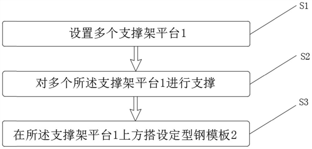
[0027] Please see attached figure 1 with Figure 3-7 , a large steel formwork construction method applied to the side wall of the shield machine receiving well station, comprising the following steps:

[0028] S1, setting a plurality of support frame platforms 1;

[0029] S2. Supporting a plurality of support frame platforms 1;

[0030] S3. Set up a shaped steel formwork 2 above the support frame platform 1 .

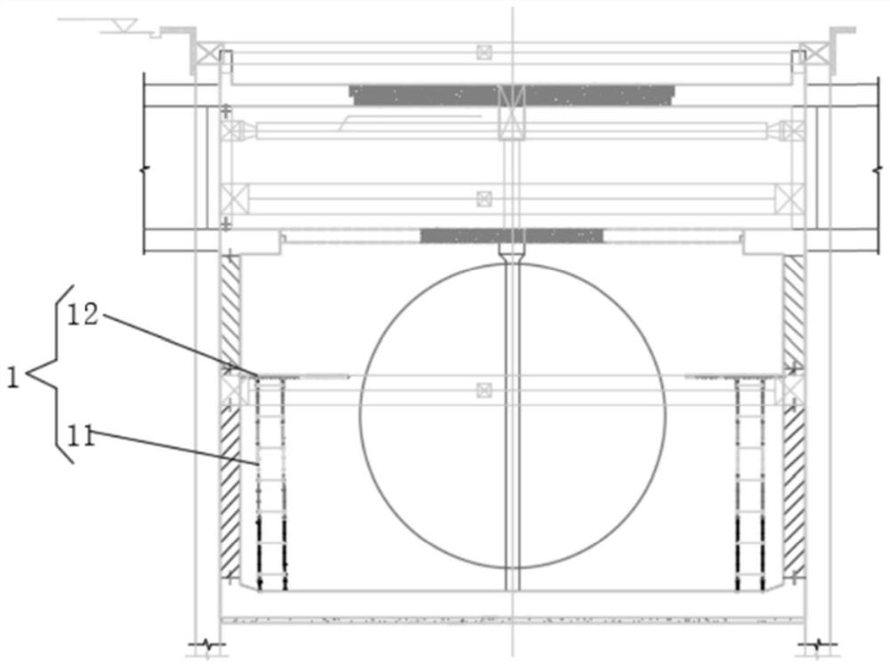
[0031] In this embodiment, the support frame platform 1 is built to the required height according to the actual needs, so that it is convenient to carry out construction at a place exceeding eight meters, and since the shaped steel formwork 2 is integrally formed, it will not affect the overall concrete The effect of pouring is guaranteed, and because the shaped steel formwork 2 is made of rigid material, there will be no water leaka...


PUM


Abstract

The invention discloses a construction method applied to a shield tunneling machine receiving well station side wall large steel mold. The construction method comprises the following steps that a plurality of supporting frame platforms are arranged; the plurality of supporting frame platforms are supported; and a profile steel template is erected above the supporting frame platform. According to the steps, the supporting frame platform can be set up to the required height according to actual requirements, so that construction can be conveniently carried out at the position exceeding eight meters, due to the fact that the set-shaped steel formwork is integrally formed, the integrity of concrete cannot be affected, the pouring effect is ensured, and due to the fact that the set-shaped steel formwork is not a traditional wood formwork, the construction cost is reduced. And therefore, water leakage is avoided.

Description

technical field [0001] The invention relates to the field of building construction, in particular to a construction method for a large steel formwork applied to the side wall of a shield machine receiving shaft station. Background technique [0002] In the prior art, a large shield machine with a diameter of 14m is generally used to carry out the shield section to complete the construction of the side wall of the station. However, this method will lead to a high floor height of the subway station, which is not conducive to meeting actual needs. The traditional single-side support formwork (big steel formwork) can be constructed up to eight meters high, and generally only wooden formwork can be used for construction in areas exceeding eight meters. However, wooden formwork construction has an impact on the integrity of concrete, especially with large concrete forms. The position where the steel molds meet is prone to water leakage, which will affect the construction effect. ...

Claims


Application Information

Patent Timeline
Patent Type & Authority Applications(China)
IPC IPC(8): E21D9/06E21D11/10
CPCE21D9/0607E21D11/003E21D11/102
Inventor 陈国飞杨占一任捷远陈俊晓奚君杰张锐李强庄星宇
Owner CHINA CONSTR EIGHT ENG DIV CORP LTD
Why Eureka
Try Eureka