Check patentability & draft patents in minutes with Patsnap Eureka AI!

Multiple-input multiple-output imaging radar system

An imaging radar, multi-output technology, applied in the field of MIMO imaging radar system, can solve the problems of expensive calculation and unrealizable airborne application

Pending Publication Date: 2022-05-13
THALES TOUR CARPE DIEM PLACE DES COROLLES ESPLANADE NORD COURBEVOIE
View PDF0 Cites 0 Cited by
  • Summary
  • Abstract
  • Description
  • Claims
  • Application Information

AI Technical Summary

Problems solved by technology

digital synthesis of the channels of the virtual array would then be computationally prohibitively expensive and therefore impractical for airborne applications

Method used


Image

  • Multiple-input multiple-output imaging radar system
  • Multiple-input multiple-output imaging radar system
  • Multiple-input multiple-output imaging radar system

Examples


Embodiment Construction

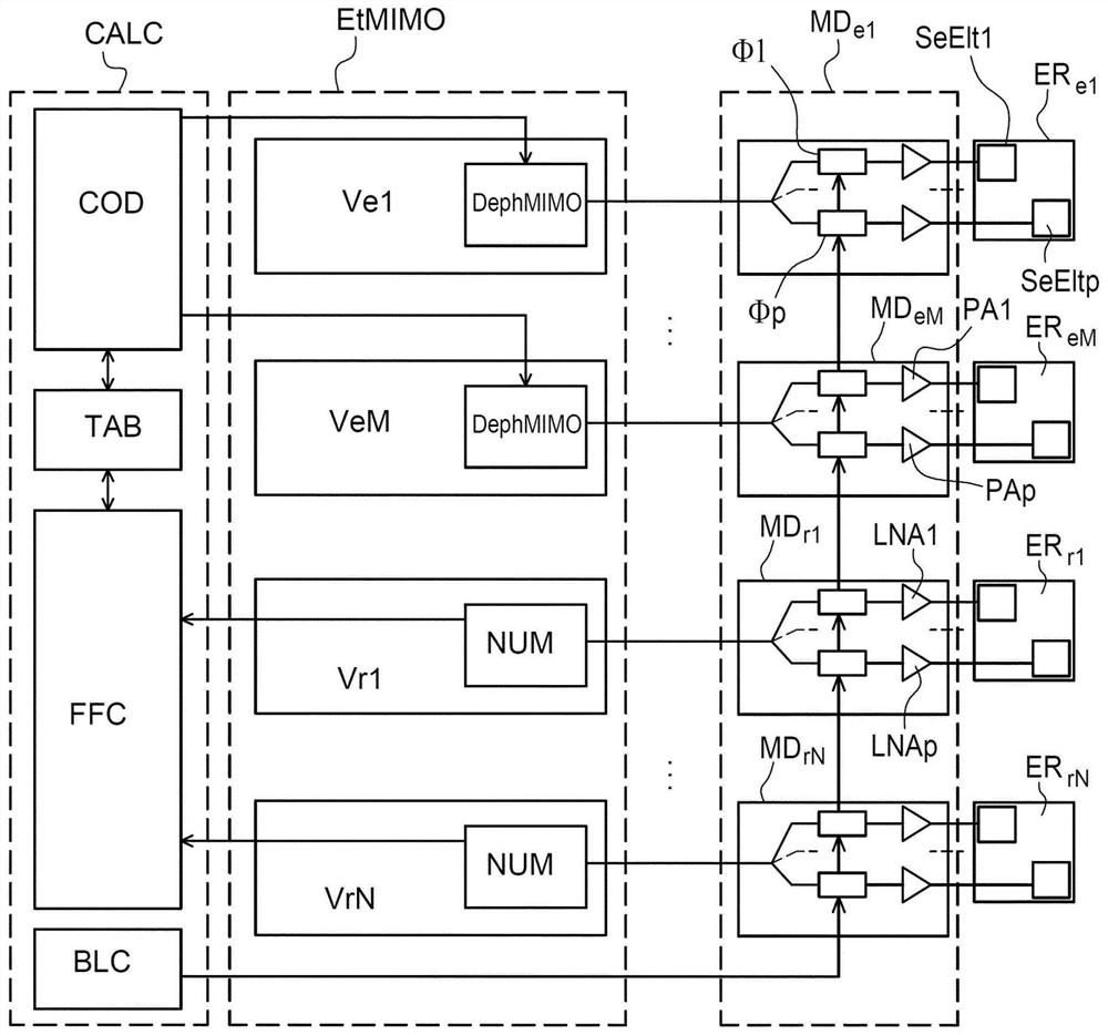
[0073] image 3 The architecture of a radar system in continuous wave mode according to the invention is shown. It should be recalled that in continuous wave mode each radiating element is associated exclusively with one transmit channel or with one receive channel.

[0074] The radar system according to the invention comprises a MIMO level EtMIMO comprising a plurality of transmit channels (Ve1 , . . . , VeM) and a plurality of receive channels (Vr1 , . . . , VrN).

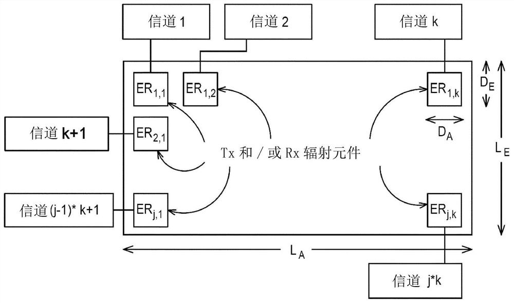
[0075] The radar system according to the invention comprises a plurality of radiating elements (ERe1, EReM, ERr1, ERrN), each radiating element (ERe1, EReM, ERr1, ERrN) being associated with a transmission channel (Ve1, ..., VeM) or with a Receive channels (Vr1, ..., VrN) are associated.

[0076] Each transmit channel has the feature of being able to apply an individual signature to the transmitted radar signal. There are many ways to obtain such a signature, such as Barker codes, DDMA coding (DDMA stands for ...


PUM


Abstract

The invention relates to a MIMO imaging radar system, comprising:-a transmission channel (Ve1, VeM); -a receiving channel; (Vr1, VrN); -co-located radiating elements (ERe1, EReM, ERr1, ERrN) forming a two-dimensional antenna array, each radiating element (ERe1, EReM, ERr1, ERrN) having a predetermined instantaneous coverage area; each radiating element is formed by a plurality of p radiating sub-elements (SeElt1, SsEltp) distributed in at least one of the two dimensions of the antenna array, the radar comprising a plurality of electronic steering modules (MDe1,..., MDrN), each connected to one radiating element, each diverting module is configured to apply a diverting command (Cmd) between all radiating sub-elements (SeElt1, SsEltp) of a given radiating element, the diverting command (Cmd) being identical from one radiating element to the next so as to move the coverage area of each radiating element in the same direction.

Description

technical field [0001] The present invention relates to MIMO imaging radar systems, to aircraft comprising such systems, and to methods for controlling MIMO imaging radar systems, MIMO being the acronym for Multiple Input Multiple Output. Background technique [0002] Imaging radars in the millimeter band (with frequencies between 30GHz and 300GHz) now allow to generate images of the aircraft's external environment under any external visibility conditions (adverse weather conditions such as snow, rain, fog, or indeed at night) and With angular resolution better than 1 degree. [0003] Specifically, during the landing phase, it is very important for the pilot to obtain as much real-time information as possible on the runway (dimensions, boundaries, whether there are obstacles on the runway). [0004] The system that allows an image of the runway to be displayed while the screen is visible is called the Enhanced Flight Vision System (by its acronym EFVS). [0005] This infor...

Claims


Application Information

Patent Timeline
IPC IPC(8): G01S13/89
CPCG01S13/89G01S13/913G01S7/4026G01S7/032H01Q3/26G01S13/00G01S13/42G01S13/878H01Q21/061H01Q1/28Y02A90/10G01S13/426G01S2013/0263H01Q3/36
Inventor 尤安·韦拉克帕斯卡·科尔尼克雷南·勒·格尔冈萨格·贝尔廷·德·拉·豪蒂埃
Owner THALES TOUR CARPE DIEM PLACE DES COROLLES ESPLANADE NORD COURBEVOIE
Features
  • R&D
  • Intellectual Property
  • Life Sciences
  • Materials
  • Tech Scout
  • Unparalleled Data Quality
  • Higher Quality Content
  • 60% Fewer Hallucinations
Learn More