Battery vacuum liquid suction device and control method thereof

A vacuum suction and battery technology, applied in battery pack parts, circuits, electrical components, etc., can solve the problems of inconvenient transportation, manufacturing difficulties, performance degradation, etc., and achieve the effect of good sealing effect, easy processing, and production cost saving.

Pending Publication Date: 2022-05-13
ZHONGYIN NINGBO BATTERY CO LTD
View PDF0 Cites 0 Cited by
  • Summary
  • Abstract
  • Description
  • Claims
  • Application Information

AI Technical Summary

Problems solved by technology

After research, the performance of alkaline dry batteries decreases after discharge or battery storage under heavy load. The main reason is that the electrolyte in the battery is reduced or dried up. Ele...

Method used


Image

  • Battery vacuum liquid suction device and control method thereof
  • Battery vacuum liquid suction device and control method thereof
  • Battery vacuum liquid suction device and control method thereof

Examples


Embodiment 2

[0080] The present invention also provides a control method for a battery vacuum cover liquid suction device, based on the battery vacuum liquid suction device described in Embodiment 1, comprising the steps of:

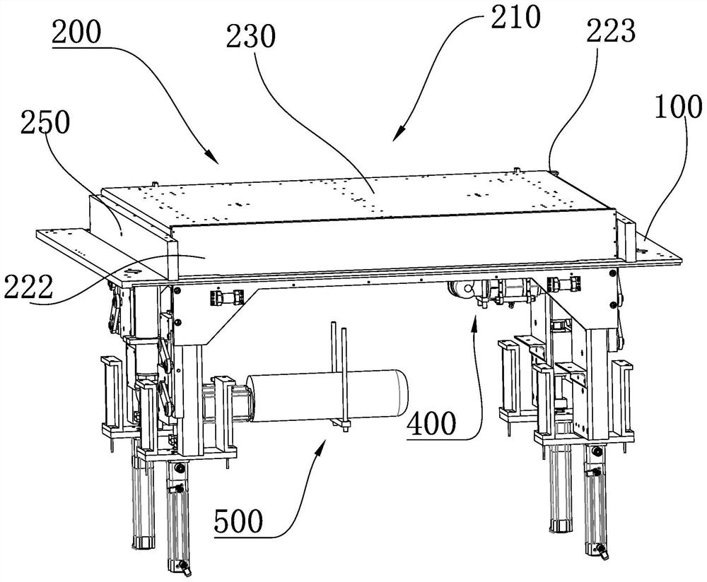
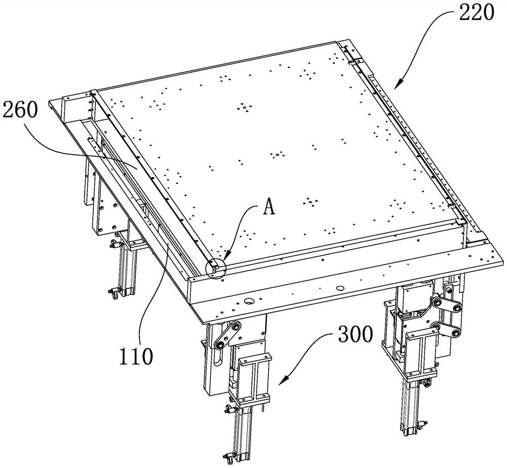
[0081] S1: Open the vacuum cover through the lifting movement of the movable plate in the vertical direction, and wait for the liquid-absorbing battery to be input into the liquid-absorbing part;

[0082] S2: closing the vacuum cover through the lifting movement of the movable plate in the vertical direction;

[0083] S3: The controller controls the vacuum component to vacuumize the chamber, and monitors the real-time vacuum degree in the chamber through a vacuum gauge;

[0084] S4: Send the monitored real-time vacuum degree to the controller through the vacuum gauge, and judge whether the real-time vacuum degree reaches the preset vacuum degree through the controller, if yes, go to step S5, if not, continue vacuuming;

[0085] S5: Control the vacuum component to st...

Embodiment 3

[0090] The present invention also provides a control method for a battery vacuum cover liquid suction device, based on the battery vacuum liquid suction device described in Embodiment 1, comprising the steps of:

[0091] S1: Open the vacuum cover through the lifting movement of the movable plate in the vertical direction, and wait for the liquid-absorbing battery to be input into the liquid-absorbing part;

[0092] S2: closing the vacuum cover through the lifting movement of the movable plate in the vertical direction;

[0093] S3: the controller controls the vacuum component to evacuate the containing cavity within a preset time;

[0094] S4: stop the work of the vacuum component, and control the release of the vacuum component by the controller to release the vacuum in the chamber until the internal and external atmospheric pressures are consistent;

[0095] S5: Steps S3-S4 are repeatedly executed, and the number of executions is judged by the controller. If the number of e...


PUM


Abstract

The invention provides a battery vacuum liquid suction device and a control method thereof, and belongs to the technical field of battery processing, the battery vacuum liquid suction device comprises a bottom plate for placing a battery tray, the bottom plate is covered with a vacuum cover, and a containing cavity for vacuum liquid suction of a battery is formed between the vacuum cover and the bottom plate, the vacuum cover comprises side plates and a top plate which are connected, and at least one side plate or top plate is arranged to be a movable plate. According to the vacuum cover, at least one movable plate is arranged on the vacuum cover, so that the structure of the whole vacuum cover is flexible and changeable, the sealing function can be completely achieved even if the size of the vacuum cover is large, meanwhile, the movable plate and the fixed plate of the vacuum cover are designed in a split mode, machining is facilitated, meanwhile, the production cost is saved, deformation can be avoided, and the vacuum cover is suitable for large-scale popularization and application. And the liquid absorption efficiency of the battery is greatly improved, so that the production quality of the battery is improved, and the service life of the battery is prolonged.

Description

technical field [0001] The invention belongs to the technical field of battery processing, and in particular relates to a battery vacuum liquid suction device and a control method thereof. Background technique [0002] With the continuous development of digital technology and the gradual popularization of digital products, the number of high-current and high-power electrical products powered by batteries is gradually increasing, and the requirements for battery performance are also getting higher and higher. The outstanding performance is to maintain excellent and durable batteries under heavy load Product performance. After research, the performance of alkaline dry batteries decreases after discharge or battery storage under heavy load. The main reason is that the electrolyte in the battery is reduced or dried up. The electrolytic solution is absorbed by means of pressure or the liquid is sucked through the vacuum cover, but the existing liquid suction vacuum cover mostly ...

Claims


Application Information

Patent Timeline
IPC IPC(8): H01M50/609
CPCH01M50/609
Inventor 张奇尧龚彪
Owner ZHONGYIN NINGBO BATTERY CO LTD
Why Eureka
Try Eureka