Multi-point angled fixation implant for multiple screws

A screw and bone anchor technology, applied in the field of orthopedic implants, can solve problems such as limiting the flexibility of bone attachment point positioning

Pending Publication Date: 2022-05-13
MEDOS INT SARL
View PDF13 Cites 0 Cited by
  • Summary
  • Abstract
  • Description
  • Claims
  • Application Information

AI Technical Summary

Problems solved by technology

[0005] Even when the bone anchor assembly is in an undamaged state, the geometry of conventional bone anchor assemblies limits flexibility in the positioning of the bone attachment point relative to a plate, rod, or other implant configuration coupled to the bone anchor assembly

Method used


Image

  • Multi-point angled fixation implant for multiple screws
  • Multi-point angled fixation implant for multiple screws
  • Multi-point angled fixation implant for multiple screws

Examples


Embodiment Construction

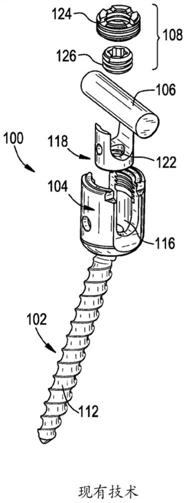
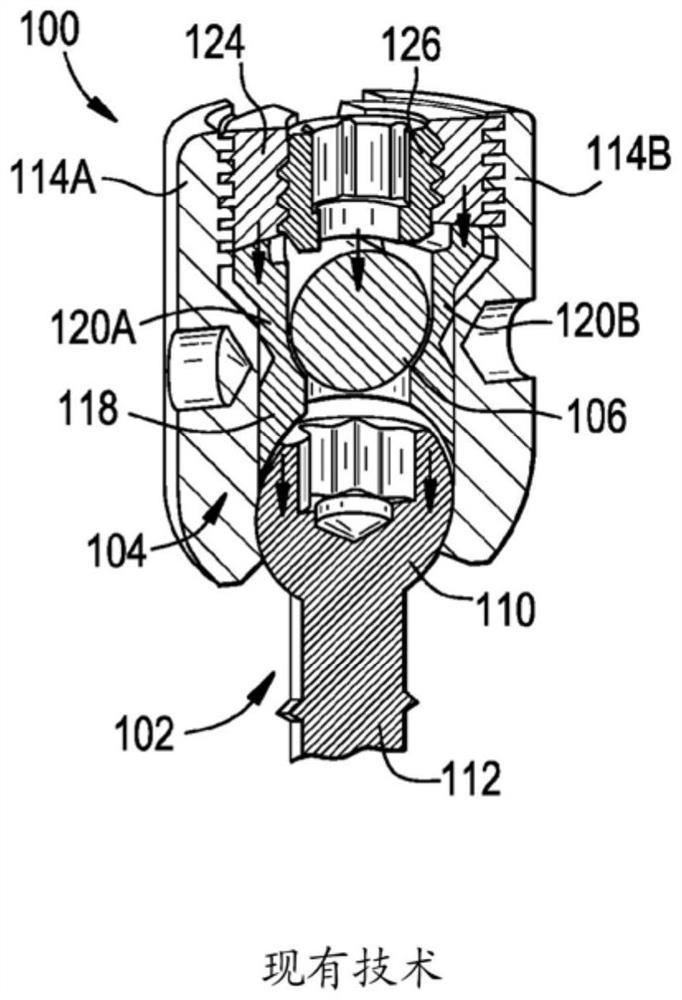
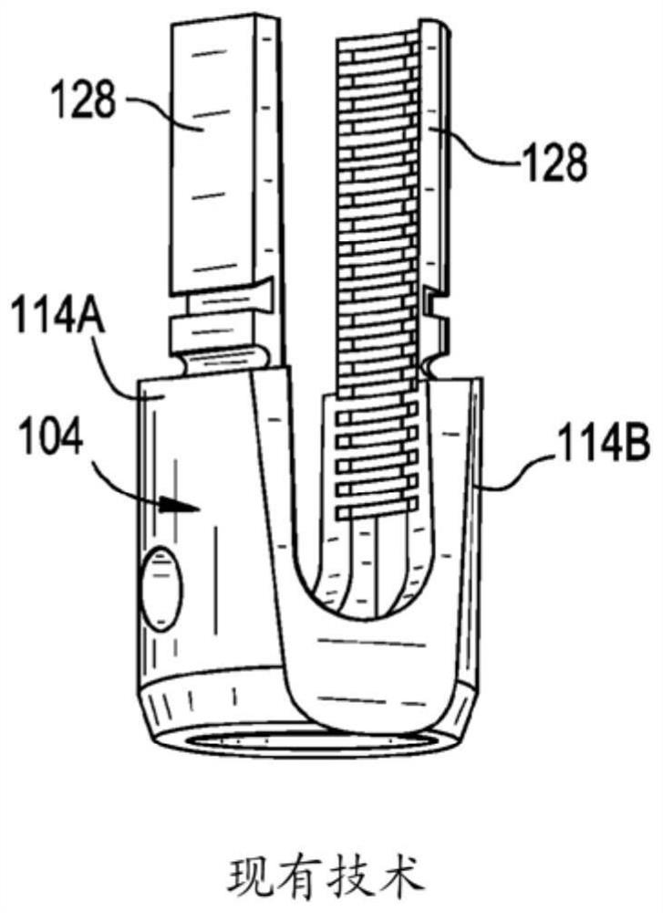
[0078] The present invention discloses a bone anchor assembly that provides improved fixation compared to conventional bone anchor assemblies. Exemplary assemblies may include brackets or wings extending downwardly from the receiver member and housing one or more secondary bone anchors that enhance the fixation of the primary bone anchors of the assembly. Another exemplary assembly may include a plate disposed between the receiver member and the rod and housing one or more auxiliary bone anchors that enhance the fixation of a primary bone anchor of the assembly. Another exemplary assembly may include hooks extending outwardly from the receiver member to hook onto an anatomical structure or another implant to enhance the fixation of the main bone anchor of the assembly. Surgical methods using the bone anchor assemblies described herein are also disclosed.

[0079] Certain exemplary embodiments will now be described to provide an overall understanding of the principles of the s...


PUM


Abstract

Disclosed herein are bone anchor assemblies and related methods that may provide improved fixation of a primary bone anchor. The bone anchor assembly may include a wing having a distal portion that may define a plurality of auxiliary bone anchor openings. Each auxiliary bone anchor opening may receive an auxiliary bone anchor that may enhance fixation of a primary bone anchor of the bone anchor assembly. The plurality of secondary bone anchor openings may be oriented such that when the wing is coupled to a primary bone anchor assembly of a vertebral segment in a first configuration, at least one secondary bone anchor may be driven to extend across a facet plane of the vertebral segment, and when coupled in a second configuration, at least one secondary bone anchor may be driven to extend across a facet plane of the vertebral segment. Each auxiliary bone anchor received within the wing may be driven to conform to the vertebral segment.

Description

technical field [0001] Orthopedic implants and related methods are disclosed herein. For example, a bone anchor assembly having multiple bone engagement points is disclosed. Background technique [0002] Bone anchor assemblies may be used in orthopedic surgery to secure bone during healing, fusion, or other procedures. For example, in spinal surgery, bone anchor assemblies may be used to secure a spinal fixation element to one or more vertebrae to rigidly or dynamically stabilize the spine. The bone anchor assembly can also be used as an articulation point for manipulating bones (eg, distracting, compressing, or rotating one vertebra relative to another, reducing long bone fractures, etc.). [0003] The integrity of the bone anchor assembly's engagement with the bone can affect the transmission of corrective biomechanical forces. Although a great deal of care is taken when placing the bone anchor assembly, the bone anchor assembly is often inserted in a damaged state. Fo...

Claims


Application Information

Patent Timeline
Patent Type & Authority Applications(China)
IPC IPC(8): A61B17/80A61B17/70A61B17/56
CPCA61B17/7059A61B17/7041A61B17/7032A61B17/7043A61B17/7067A61B17/7044A61B17/7058A61B17/7035A61B17/8057A61B17/7002A61B2017/564
Inventor K·李C·拉姆齐J·R·郝金斯A·蒙特罗
Owner MEDOS INT SARL
Why Eureka
Try Eureka