
Method and control system for controlling compressor output of gas turbine engine

A technology for gas turbines and engines, used in engine control, turbine/propulsion fuel delivery systems, engine components, etc., to solve problems such as overspeed, reducing the severity and duration of transient conditions, compressor surge, etc.

Pending Publication Date: 2022-05-13
SOLAR TURBINES
View PDF1 Cites 0 Cited by
  • Summary
  • Abstract
  • Description
  • Claims
  • Application Information

AI Technical Summary

Problems solved by technology

This reduces the severity and duration of transient conditions, resulting in reduced operational and reliability issues such as overspeed, compressor surge and high turbine temperatures

Method used


Image

  • Method and control system for controlling compressor output of gas turbine engine
  • Method and control system for controlling compressor output of gas turbine engine
  • Method and control system for controlling compressor output of gas turbine engine

Examples


Embodiment Construction

[0010] The detailed description, set forth below in conjunction with the accompanying drawings, is intended as a description of various embodiments and is not intended to represent the only embodiments in which the invention may be practiced. The detailed description includes specific details in order to provide a thorough understanding of the embodiments. It will be apparent, however, to one skilled in the art that embodiments of the invention may be practiced without these specific details. In some instances, well-known structures and components are shown in simplified form for clarity of description.

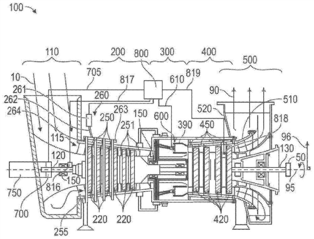
[0011] figure 1 is a schematic diagram of an exemplary gas turbine engine. Some surfaces are omitted or exaggerated for clarity and ease of illustration. Furthermore, the invention may refer to both forward and backward directions. In general, all references to "forward" and "rearward" relate to the direction of flow of the primary air (ie, the air used for the combustion...


PUM


Abstract

A method and control system for controlling a shaft speed of a gas turbine engine (100) is disclosed. The power output of the gas turbine engine (100) may vary and be below a desired output level due to operating conditions such as ambient temperature and altitude. These operating conditions may result in lower rotational speeds of a gas generator shaft (120) of the turbine engine (100) and lower operating temperatures within or near a turbine (400) of the gas turbine engine (100) and result in smaller power output. Additional fuel may be added to increase the power of the gas generator shaft (120) and increase the turbine temperature of the gas turbine engine (100). The power transfer device (700) may be used to remove and increase the power of the gas generator shaft (120) to increase and maintain the speed of the gas generator shaft (120) and the temperature of the turbine (400) at maximum levels and result in higher power output.

Description

technical field [0001] The present invention relates generally to gas turbine engines. More specifically, the present application relates to a method and control system for controlling compressor output of a gas turbine engine. Background technique [0002] By designing the gas generator shaft speed and simultaneously satisfying the maximum power turbine temperature limit, a gas turbine engine can maximize output power and efficiency for a given ambient temperature. This is called matching temperature. In a typical turbine engine, this occurs at a single ambient temperature. However, if power can be imported or withdrawn independently from the gas generator shaft, then optimization can be maintained at all ambient temperatures, increasing maximum power capability. [0003] US Patent No. 7,188,475 to McGinley et al. describes a twin rotor gas turbine engine for driving a variable speed load, such as a generator or a fan / propeller of an aircraft engine. Gas turbine engines...

Claims


Application Information

Patent Timeline
Patent Type & Authority Applications(China)
IPC IPC(8): F02C7/22F02C9/28
CPCF02C7/22F02C9/28F05D2240/60F05D2270/304F05D2270/303F05D2240/35F05D2270/023F02C3/10F05D2220/76
Inventor P·戴维斯
Owner SOLAR TURBINES
Learn More