Close-fit riveting structure and riveting method for string of radiating fin groups and heat pipes

A heat dissipation fin group and a technology of heat dissipation fins, which are applied in heat exchange equipment and other directions, can solve problems such as changes in the shape and size of the heat dissipation fin group, unsatisfactory overall structural strength, and influence on the overall structural strength, so as to improve the heat dissipation effect, The riveting method is simple and reliable, and the overall structural strength is good

Pending Publication Date: 2022-05-17
DONG GUAN HAN XU HARDWARE & PLASTIC TECH CO LTD
View PDF1 Cites 0 Cited by
  • Summary
  • Abstract
  • Description
  • Claims
  • Application Information

AI Technical Summary

Problems solved by technology

This kind of structure, its through-hole must obviously be bigger than heat pipe, like this, after forming heat dissipation fin group, just can make heat pipe penetrate in the through-hole of a plurality of heat dissipation fins, although annular protruding wall can contact heat. However, since the passage is closed-loop, even if the extrusion deformation is caused by strong compression, there will still be a gap between the through hole and the heat pipe, which will affect the heat dissipation performance
Moreover, the heat dissipation fins are only fastened by fasteners. Although they can be strung together, the overall structural strength after being strung is not ideal, especially when subjected to strong pressure, it is easy to cause changes in the external dimensions of the heat dissipation fin group, which affects the overall structure. strength

Method used


Image

  • Close-fit riveting structure and riveting method for string of radiating fin groups and heat pipes
  • Close-fit riveting structure and riveting method for string of radiating fin groups and heat pipes
  • Close-fit riveting structure and riveting method for string of radiating fin groups and heat pipes

Examples


Embodiment Construction

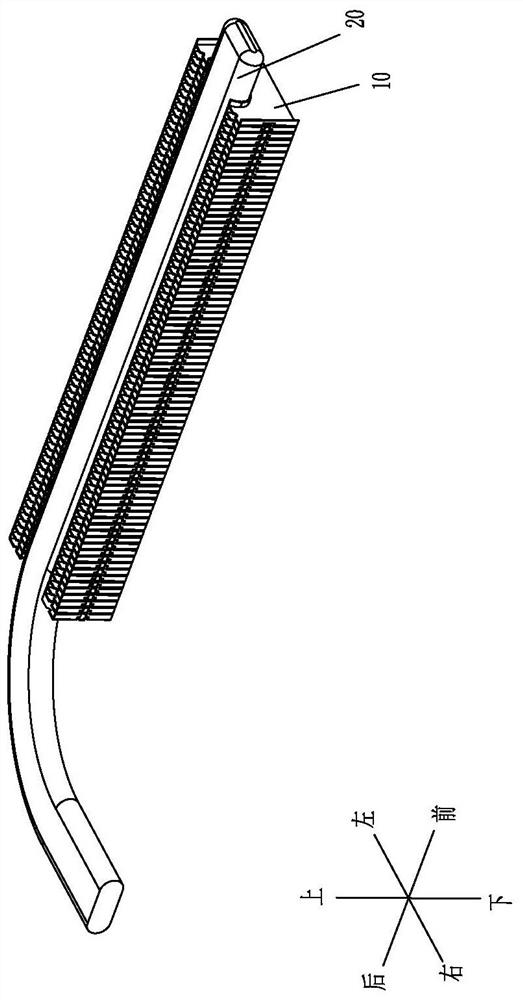
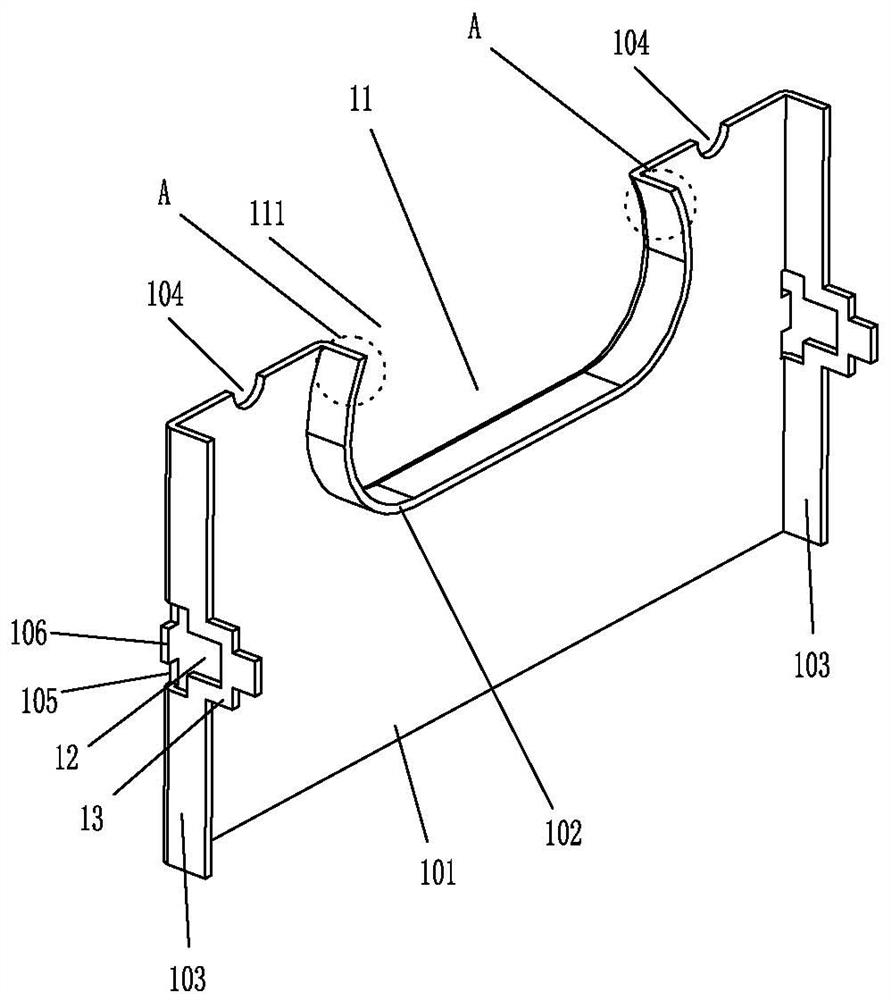
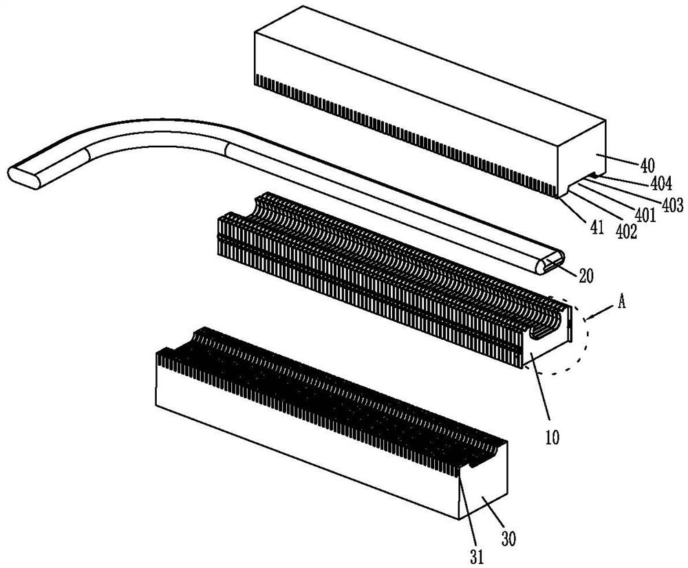
[0058] Please refer to Figure 1 to Figure 17 As shown, it shows the specific structure of various embodiments of the present invention.

[0059] In the description of the present invention, it should be noted that for orientation words, if there are terms such as "upper", "lower", "front", "back", "left", "right", etc., indicating that the orientation and positional relationship is based on The orientations or positional relationships shown in the drawings are only for the convenience of describing the present invention and simplifying the description, rather than indicating or implying that the referred device or element must have a specific orientation, be constructed and operated in a specific orientation, and should not be construed as limiting the present invention. The specific protection scope of the invention.

[0060] Such as Figure 1 to Figure 5 Shown, it has shown the specific structure of embodiment one:

[0061] A tight-fit riveting structure of a series of h...


PUM


Abstract

The invention discloses a close-fit riveting structure and riveting method of a string of heat dissipation fin groups and heat pipes, the close-fit riveting structure comprises a plurality of heat dissipation fin buckling groups and at least one heat pipe, the heat dissipation fin groups are internally provided with accommodating grooves for accommodating the heat pipes, and the heat pipes are located in the accommodating grooves. The two sides of the containing groove in the heat dissipation fin set are riveted, so that the heat pipe is tightly matched and fixed in the containing groove in a riveting mode; the periphery of the containing groove of the fin body is integrally bent forwards to form a first bent edge, and the first bent edge and the fin body are bent to form an L shape. The two sides of the fin body are integrally bent forwards to form buckling pieces, buckling holes capable of containing the buckling pieces are formed in the buckling pieces, and the buckling pieces of the heat dissipation fins are buckled in the buckling holes of the buckling pieces of the adjacent heat dissipation fins on the front side. After the heat pipe is located in the containing groove of the heat dissipation fin set buckled into the string, the first riveting deformation portions on the two sides of the communicating opening of the containing groove are riveted towards the surface of the heat pipe, and the first riveting deformation portions deform to clamp the heat pipe in a close fit mode.

Description

technical field [0001] The invention relates to the technology in the field of heat dissipation devices, in particular to a tight-fit riveting structure and riveting method of a series of heat dissipation fin groups and heat pipes. Background technique [0002] At present, the heat dissipation structure formed by the combination of heat dissipation fins and heat pipes is very common, and the tightness of the combination of heat dissipation fins and heat pipes directly affects the heat dissipation performance. [0003] For example, in CN100450660C, it discloses a pressing forming method of heat pipes and heat dissipation fins, which firstly uses fasteners to buckle the heat dissipation fins to form heat dissipation fins arranged at intervals by providing a closed-loop through hole on the heat dissipation fins. group, and then penetrate the heat pipe into the through holes of multiple heat dissipation fins, and then carry out the pressing molding process, that is, cooperate wi...

Claims


Application Information

Patent Timeline
IPC IPC(8): B21D39/00B21D53/06
CPCB21D39/00B21D53/06F28D15/0233F28D15/0275
Inventor 黄崇贤
Owner DONG GUAN HAN XU HARDWARE & PLASTIC TECH CO LTD
Why Eureka
Try Eureka