Check patentability & draft patents in minutes with Patsnap Eureka AI!

Guide wire driving device of vascular intervention robot

A driving device and robot technology, applied in the field of medical equipment, can solve the problems of heavy physical injury, long-term training, hand tremors, etc., and achieve the effects of reducing labor intensity and radiation damage, convenient installation and detachment operation, and convenient installation

Pending Publication Date: 2022-05-20
山东威高医疗科技有限公司
View PDF0 Cites 3 Cited by
  • Summary
  • Abstract
  • Description
  • Claims
  • Application Information

AI Technical Summary

Benefits of technology

This technology helps reduce radiation exposure during medical procedures while also improving efficiency for surgery operations. It uses an electric or magnetic driving system that rotatingly moves a guiding rod along its length without physically touching any other objects around them. By doing this, less effort from surgeons reduces their workload and minimizes potential harm caused due to contact. Additionally, there is no physical connection made when attaching the two parts together, making it easy to separate them easily after they have been used again. Overall, these improvements improve patient outcomes and make surgery more efficient.

Problems solved by technology

The technical problem addressed by this patented solution is how to improve the efficiency and safety of performing vascualintervention surgeries while reducing their risks associated therewith during prolonged exposure periods without causing damage from excessive pressure on healthy areas such as skin caused by manual handling techniques used beforehand.

Method used


Image

  • Guide wire driving device of vascular intervention robot
  • Guide wire driving device of vascular intervention robot
  • Guide wire driving device of vascular intervention robot

Examples


Embodiment Construction

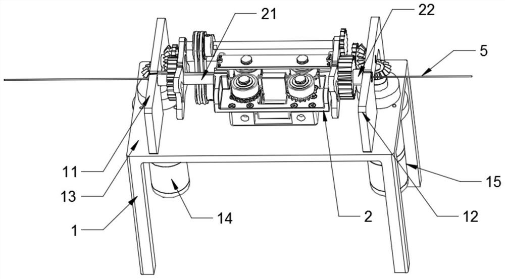
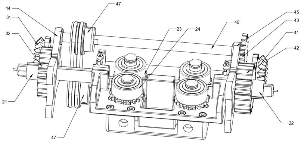
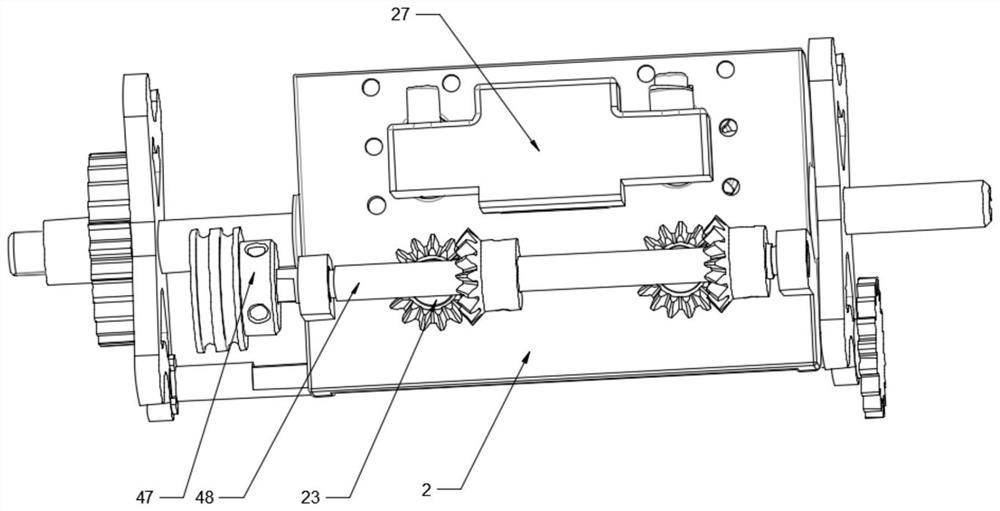
[0050] as Figure 1-6 As shown, the present invention:

[0051] A vascular interventional robot guide wire drive device, comprising: bracket 1, first drive motor, first transmission assembly, second drive motor, second transmission assembly and substrate 2, bracket comprising table 13, table 13 is provided perpendicular to the table 13 and parallel to each other left mount 11 and right mount 12, both ends of the substrate 2 are provided with axial overlapping left end axis 21 and right shaft 22, left and right mounts with axle holes in conjunction with the left and right end shafts, The left and right shafts are connected to the left mount and right mount rotation, respectively, and the center shaft of the left and right shafts is provided with a guide wire hole, and the axis of the guide wire hole is located on the side of the substrate 2. The first drive motor 14 and the second drive motor 15 are provided on the lower side of the table 13, the first drive motor 14 and the second ...


PUM


Abstract

The invention provides a vascular intervention robot guide wire driving device which comprises a support, a first driving motor, a first transmission assembly, a second driving motor, a second transmission assembly and a base plate, the two ends of the base plate are provided with a left end shaft and a right end shaft with the axes coincident, and the left end shaft and the right end shaft are rotationally connected with the support. A wire guide hole is formed in the middle shaft of the left end shaft and the right end shaft, the first driving motor drives the base plate to rotate through the first transmission assembly, and a wire guide clamping roller set is arranged on the base plate. The guide wire has the beneficial effects that due to the adoption of the technical scheme, the guide wire can be driven by the motor to rotate and axially move, so that the labor intensity and irradiation damage of doctors are greatly reduced.

Description


Claims


Application Information

Patent Timeline
Owner 山东威高医疗科技有限公司
Features
  • R&D
  • Intellectual Property
  • Life Sciences
  • Materials
  • Tech Scout
  • Unparalleled Data Quality
  • Higher Quality Content
  • 60% Fewer Hallucinations
Learn More