A voltage stabilizer for engine cooling system

A technology of engine cooling and voltage stabilizing device, which is applied in the direction of engine cooling, engine components, machines/engines, etc. It can solve the problems of inconvenience, poor flexibility, inaccurate coolant pressure, etc., and achieve ingenious design and increased sealing , the effect of precise accuracy

Active Publication Date: 2022-07-12
HUAFENG POWER
View PDF6 Cites 0 Cited by
  • Summary
  • Abstract
  • Description
  • Claims
  • Application Information

AI Technical Summary

Problems solved by technology

[0003] For example, the application number is CN02247839.6, which discloses a forced pressure relief and anti-scalding water tank cover. At present, the water tank cover on the water tank has the function of adjusting the pressure of the coolant in the water tank, and can adjust the cooling hydraulic pressure in the water tank in time. However, the sealing part of the current water tank cover is made of corrosion-resistant rubber material, and the deformable characteristics of rubber are used to open and close the seal. service life
[0004] At the same time, the water tank cover is provided with a spring with a fixed compression force, and the cooling liquid inside and out of the water tank is controlled by the preset spring compression force. When the cooling liquid is discharged to the outside, it is discharged through the circumferential edge of the rubber pad, which is consistent with the spring. The force between them is non-radial, so the spring is not accurate for controlling the pressure of the coolant in the water tank, it is difficult to control the preset pressure value of the coolant, and the best cooling effect of the coolant cannot be guaranteed.
[0005] In summary, there are obviously inconveniences and defects in the actual use of the existing technology, so it is necessary to improve

Method used


Image

  • A voltage stabilizer for engine cooling system
  • A voltage stabilizer for engine cooling system
  • A voltage stabilizer for engine cooling system

Examples


Embodiment

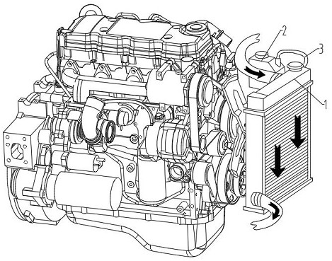
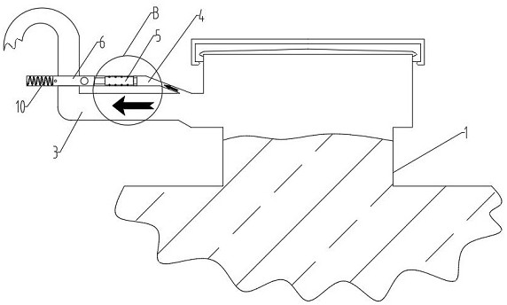
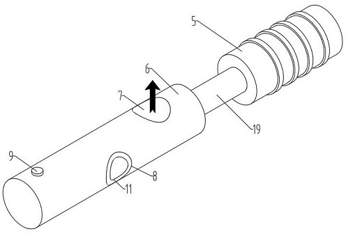
[0033] Example: as Figure 1-10 As shown, a voltage stabilizer for an engine cooling system includes an engine water-cooling circulation pipeline, a heat sink, and a main water tank 1. The top of the main water tank 1 is connected to an auxiliary water tank 2 through a pressure relief pipe 3. The pressure relief The side of the pipe 3 close to the main water tank 1 is provided with a pressure pipe 4 that communicates with it. The pressure pipe 4 is provided with a control component for controlling the internal pressure value of the main water tank 1; the control component includes a coaxial and sliding A pressure relief rod sealed inside the pressure pipe 4, the front section of the pressure relief rod is a sliding head 5 that matches the inner wall of the pressure pipe 4, and a plurality of sealing rings to enhance sealing are sleeved on the sliding head 5; The rear section of the pressure relief rod is a cylindrical control part 6 arranged coaxially with the sliding head 5 ,...


PUM


Abstract

The invention provides a voltage stabilization device for an engine cooling system, comprising an engine water-cooling circulation pipeline, radiating fins, and a main water tank. The top of the main water tank is connected to an auxiliary water tank through a pressure relief pipe, and the pressure relief pipe is close to the top of the main water tank. One side of the main water tank is provided with a pressure pipe that communicates with it, and a control component for controlling the internal pressure value of the main water tank is arranged in the pressure pipe; It is accurately located in the pressure relief pipe, and at the same time, the chute and the limit column can accurately place the pressure relief hole in the pressure relief pipe, which effectively increases the service life of the pressure relief device of the water tank, and is more accurate for the pressure relief of the water tank, ensuring a relatively constant pressure. Under optimum pressure, the cooling efficiency of the engine is maximized.

Description

technical field [0001] The present invention relates to the technical field of engine cooling systems, in particular to a voltage stabilization device for an engine cooling system. Background technique [0002] The heat generated during the operation of the engine needs to be exchanged by the cooling system. The most common cooling system is the water cooling system. The coolant circulation in the water cooling system is used to bring the heat of the engine to the heat sink, and the heat sink is blown by the fan of the engine. Cooling is carried out, and the cooled coolant enters the engine again for heat dissipation and circulation system; the coolant is all in the water tank and the circulation pipeline, and the water tank is provided with a water tank cover for regular filling of the coolant. [0003] For example, as disclosed in the application number CN02247839.6 for a forced pressure relief and anti-scalding water tank cover, the water tank covers currently installed o...

Claims


Application Information

Patent Timeline
Patent Type & Authority Patents(China)
IPC IPC(8): F01P11/02F01P7/14
CPCF01P11/0276F01P7/14F01P2007/146
Inventor 王国辉邵明鹏童顺波李国涛周茂森
Owner HUAFENG POWER
Why Eureka
Try Eureka