A multi-angle rotating mechanism for welding and processing of integrated circuit components

A technology of integrated circuits and rotating mechanisms, applied in welding equipment, metal processing, printed circuits, etc., can solve the problems of reducing processing efficiency and achieve the effect of cooling work

Active Publication Date: 2022-06-21
广州市星康科技有限公司
View PDF5 Cites 0 Cited by
  • Summary
  • Abstract
  • Description
  • Claims
  • Application Information

AI Technical Summary

Problems solved by technology

[0003] The integrated circuit needs to be welded during processing, and the integrated circuit board is clamped and fixed for welding. However, since the position of the components in each orientation of the circuit board is different, it is necessary to rotate the circuit board during processing to adjust the orientation. It provides convenience for welding processing, but the general adjustment method is basically manual, which is regular. At the same time, too many hands touching the circuit board may cause damage to the surface of the circuit board. It is easy to rotate, and it needs to wait for the solder joints to cool down, which further reduces the processing efficiency. Therefore, a multi-angle rotating mechanism for welding and processing of integrated circuit components is needed to improve the deficiencies of the prior art.

Method used


Image

  • A multi-angle rotating mechanism for welding and processing of integrated circuit components
  • A multi-angle rotating mechanism for welding and processing of integrated circuit components
  • A multi-angle rotating mechanism for welding and processing of integrated circuit components

Examples


Embodiment 1

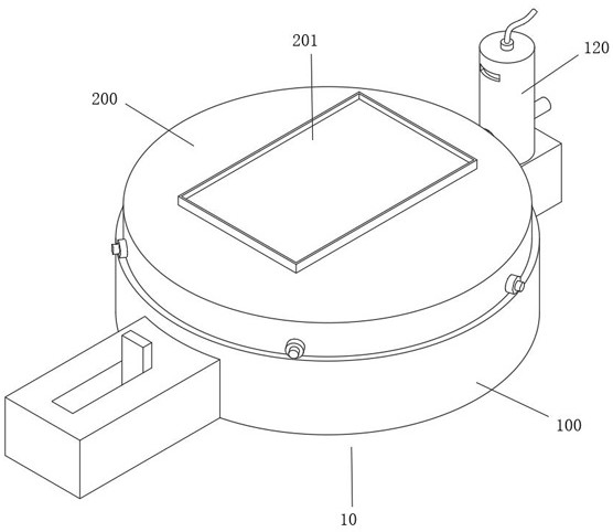
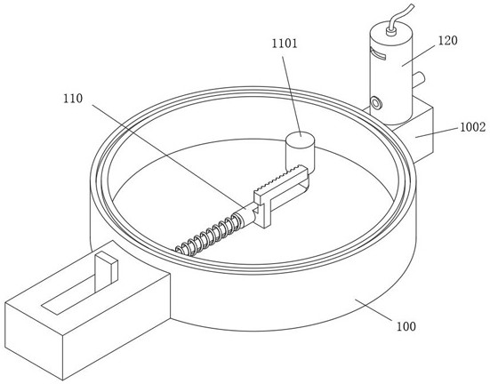
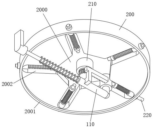
[0047] see figure 1 As shown, the purpose of this embodiment is to provide a multi-angle rotating mechanism for welding and processing integrated circuit components, including a rotating device 10. In this embodiment, the rotating device 10 at least includes a base 100 and a rotating base 200 located above the base 100. , a rotating plate 201 is installed above the rotating seat 200, and its main function is to place the integrated circuit components. Considering the need to rotate the components, according to Figure 2-Figure 3 As shown, in this embodiment, the bottom surface of the rotating base 200 is provided with a rotating edge 2001, the top surface of the base 100 is provided with a rotating track 1001, and the rotating edge 2001 is rotatably connected with the rotating track 1001, and its main function is to facilitate the angle of the components on the rotating plate 201. adjust.

[0048] Considering the need to drive the rotating base 200 to rotate, please refer to ...

Embodiment 2

[0052] On the basis of the above, considering that it is necessary to reset the column 110 after sliding, and the rotating base 200 will not be rotated in the reverse direction during reset, please refer to Figure 6-Figure 7 As shown, in this embodiment, a tooth cavity 2100 is formed inside the rotating column 210 , a plurality of tooth gaps are formed on the surface of the tooth cavity 2100 , and a rotating shaft 212 is provided at the center of the top surface of the gear 211 , and the rotating shaft 212 is rotatably connected to the tooth cavity 2100 Inside, the rotating shaft 212 is rotatably connected to the push block 2122 through the rotating block 2121 provided on the surface. The push block 2122 is inserted and matched with the tooth gap. The rotating block 2121 is located on the front surface of the push block 2122. It is used to stop the push block 2122 from rotating counterclockwise. When the gear 211 rotates clockwise, it can drive the push block 2122 to be insert...

Embodiment 3

[0056] On the basis of the above, in order to process the components, the surface of the components needs to be air-cooled at the same time, please refer to Figure 8-Figure 10 As shown, the base 100 is installed with an air tank 120 through a mounting block 1002 provided at the front end, an air cavity 1200 is opened inside the air tank 120, and an air intake pipe 1203 is connected to the top of the air cavity 1200, and its main purpose is to cool the gas into the air cavity Inside the 1200, the air tank 120 is slidably connected to a sliding column 121 through a jack 1201 provided on the rear surface of the bottom end. A connecting rod 1211 is fixed on the upper surface of the sliding column 121. There are limit rods 1205 located on both sides of the connecting rod 1211. The connecting rod 1211 is slidably connected to the interior of the limit rod 1205, and its main function is to stabilize the sliding of the connecting rod 1211. The air outlet 1202 is provided on the rear s...


PUM


Abstract

The invention relates to the technical field of integrated circuit processing, in particular to a multi-angle rotating mechanism for welding and processing integrated circuit components. It includes a rotating device. The rotating device at least includes a base and a rotating seat above the base. A rotating plate for placing components is installed above the rotating seat. The track is rotated and connected, and the front end of the base is equipped with a mounting block. The mounting block is equipped with a gas tank, and an air cavity for storing cooling gas is opened inside the gas tank; the rotating seat is driven to rotate by pulling the pull plate, and the round block is driven to slide out and slide Inside the cavity, the round block loses its thrust on the push rod and automatically resets. When the push rod is reset, it drives the sliding column to reset, so that the closing block is inserted into the air outlet to close the air outlet. This device can open the air outlet when the rotating seat is turned. Combination, that is, to meet the rotation of the components, but also to meet the cooling work of the components during processing.

Description

technical field [0001] The invention relates to the technical field of integrated circuit processing, in particular to a multi-angle rotating mechanism for welding and processing integrated circuit components. Background technique [0002] An integrated circuit is a miniature electronic device or component that uses a certain process to interconnect components and wirings such as transistors, resistors, capacitors and inductors required in a circuit, and is fabricated on a small or several small semiconductor wafers or On a dielectric substrate, and then packaged in a package, it becomes a miniature structure with the required circuit functions. [0003] The integrated circuit needs to be welded during processing, and the integrated circuit board is clamped and fixed for welding. However, due to the different positions of the components in each orientation of the circuit board, it is necessary to rotate the circuit board during processing to adjust the orientation. It provi...

Claims


Application Information

Patent Timeline
Patent Type & Authority Patents(China)
IPC IPC(8): B23K37/047B23K37/00B23K101/42
CPCB23K37/047B23K37/003B23K2101/42
Inventor 魏春华
Owner 广州市星康科技有限公司
Why Eureka
Try Eureka