Highway isolation pier device capable of moving quickly

A fast-moving and isolated pier technology, applied to road safety devices, roads, roads, etc., can solve problems such as difficult disassembly and assembly, and achieve the effect of ensuring anti-collision ability and convenient movement

Inactive Publication Date: 2022-05-24
HUNAN INSTITUTE OF ENGINEERING
View PDF0 Cites 0 Cited by
  • Summary
  • Abstract
  • Description
  • Claims
  • Application Information

AI Technical Summary

Problems solved by technology

[0003] At present, my country's highway isolation piers are basically fixed, and disassembly and assembly are very difficult. Using the existing fixed isolation piers, it is difficult to solve the problem of periodic one-way congestion by changing the number of one-way lanes in an economical way

Method used


Image

  • Highway isolation pier device capable of moving quickly
  • Highway isolation pier device capable of moving quickly
  • Highway isolation pier device capable of moving quickly

Examples


Embodiment 1

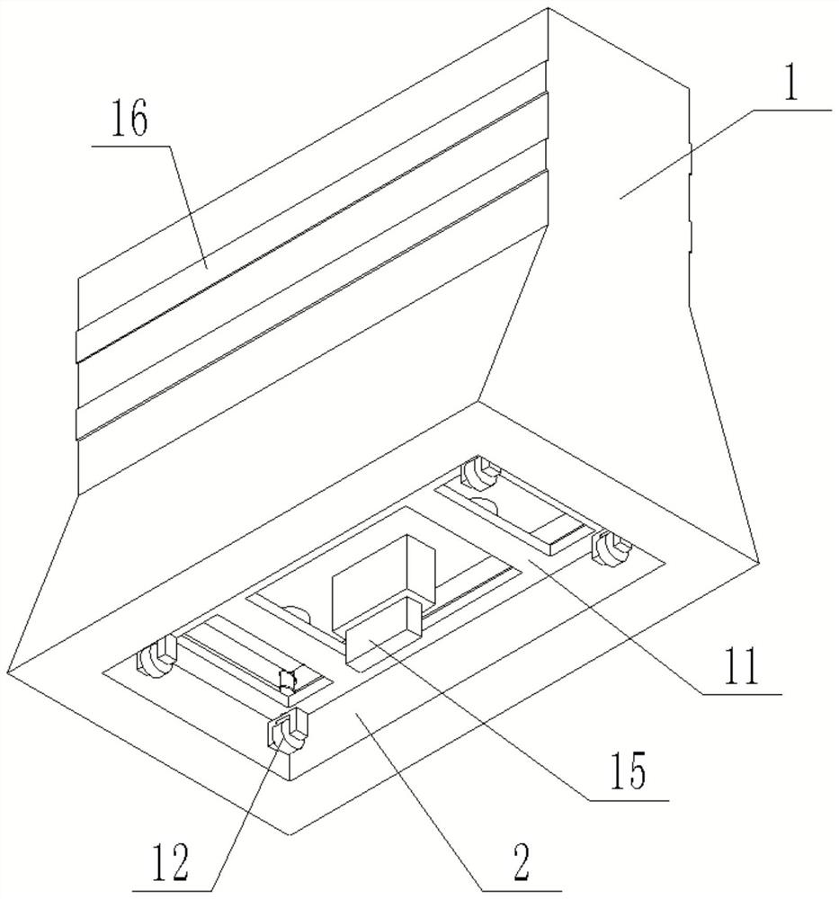
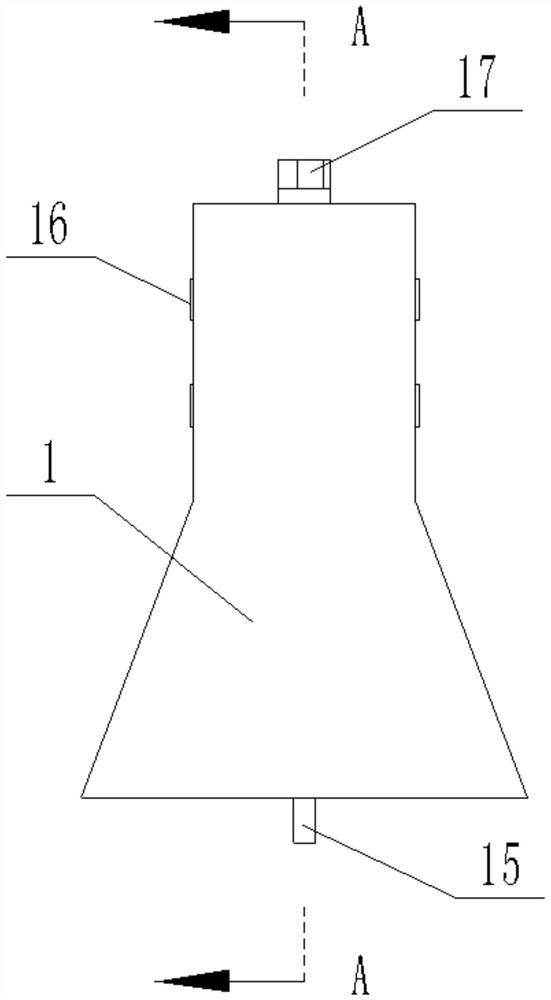
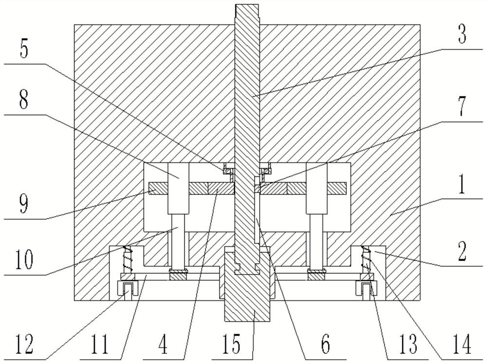
[0023] The present invention provides a fast-moving highway isolation pier device, comprising a pier body 1, a bottom of the pier body 1 is provided with an embedded groove 2 along a vertical direction, and a moving mechanism for moving the pier body 1 is arranged in the embedded groove 2; 1. A connecting column 3 is screwed in the middle part along the vertical direction, and the two ends of the connecting column 3 respectively penetrate the top end of the pier body 1 and the bottom end of the pier body 1; Above, a transmission component is installed in the equipment cavity, and the connecting column 3 is driven and matched with the moving mechanism through the transmission component.

[0024] Further, in order to facilitate the fixing or unfixing of the pier body 1 through the connecting column 3, and at the same time, the connecting column 3 is used to control the lifting and lowering of the moving mechanism, so as to facilitate the movement of the pier body 1, the transmiss...

Embodiment 2

[0032]The only difference between this embodiment and the first embodiment is that a groove 19 is formed at the bottom end of the positioning block 15, and a push block 20 is arranged in the groove 19. The section of the push block 20 is an isosceles trapezoid, and the push block A second telescopic rod 21 is fixedly connected to the top of the second telescopic rod 21 , the top of the second telescopic rod 21 is fixedly connected to the bottom of the groove 19 , a second spring 22 is sleeved outside the second telescopic rod 21 , and the two ends of the second spring 22 are respectively Abutting with the push block 20 and the groove bottom of the groove 19; a communication hole is symmetrically opened on the groove wall of the groove 19 on both sides of the push block 20, and the limit block 23 is slidably connected in the communication hole, and the limit block 23 is far from the top The end surface of the push block 20 is a rough surface, and the end surface of the limit blo...


PUM


Abstract

The highway isolation pier device capable of moving rapidly comprises a pier body, an embedding groove is formed in the bottom of the pier body in the vertical direction, and a moving mechanism used for moving the pier body is arranged in the embedding groove; the middle of the pier body is in threaded connection with a connecting column in the vertical direction. The two ends of the connecting column penetrate through the top end and the bottom end of the pier body correspondingly. An equipment cavity is formed in the middle of the pier body and located over the caulking groove, a transmission assembly is installed in the equipment cavity, and the connecting column is in transmission fit with the moving mechanism through the transmission assembly. According to the road barrier device capable of rapidly moving, the moving mechanism is arranged at the bottom of the barrier body, the position of the moving mechanism in the caulking groove is controlled through the connecting column, the moving mechanism extends out of the caulking groove when the barrier needs to move, and the moving mechanism enters the caulking groove when the barrier needs to be fixed; while the road barrier is convenient to move, the anti-collision capability of the road barrier can be ensured, and the defects in the prior art are overcome.

Description

technical field [0001] The invention relates to the technical field of traffic facilities, in particular to a fast-moving highway isolation pier device. Background technique [0002] The existing huge number of cars has brought huge pressure on traffic. Although many highways have been widened, it is still difficult to meet normal traffic. Especially during the peak period of population flow during the Spring Festival, traffic congestion is more serious. It is worth noting that the congestion of urban expressways and expressways is one-way, the direction of returning home is congested a year ago, and the direction of entering the city after the year is congested, while the reverse lanes are sparsely populated. If the number of traditional two-way symmetrical lanes can be changed by moving highway isolation piers before the arrival of the peak traffic period, not only can the existing highway lane resources be fully utilized, but also the pressure of periodic one-way traffic...

Claims


Application Information

Patent Timeline
Patent Type & Authority Applications(China)
IPC IPC(8): E01F15/00E01F9/619E01F9/692
CPCE01F15/003E01F9/619E01F9/692Y02A30/60
Inventor 李盛南李小华任振华曾宪桃王军梁桥刘杰曾智李玉彭辉华段建刘兆丰周文权张馨尤刘延状马凯汪勤用蔡诚秀胡艺腾
Owner HUNAN INSTITUTE OF ENGINEERING
Why Eureka
Try Eureka