Detection line for ferrite magnetic shoe passing through go gauge

A technology of ferrite magnetism and detection lines, which is applied in the direction of measuring devices, mechanical measuring devices, instruments, etc., can solve the problems of magnetic tile over-gauge failure, misjudgment, and detection line stuck quality, etc., to achieve smooth operation rhythm and technical Reliable solutions and the effect of enhancing product value

Pending Publication Date: 2022-05-24
合肥市小飞飞智能科技有限公司
1 Cites 0 Cited by

AI-Extracted Technical Summary

Problems solved by technology

It is difficult to have a detection device compatible with so many types of magnetic tiles
[0005] 2. At present, the most advanced visual inspection equipment or laser inspection equipment on the market cannot detect the comprehensive size of the magnetic tile shape and its deformation, that is, the maximum actual effective size, and the optical inspection equipment is too expensive to be popularized.
[0006] 3. At present, the manufacturer adopts manual manual inspection, but the fastest manual operation speed is 60PCS/min, and this efficiency is not sustainable
[0009] The above-m...

Method used

The operation of receiving tiles is as follows: set the magnetic tiles at the end of the conveying surface upright, and gather them forward, so ...

Abstract

The invention discloses a ferrite magnetic shoe passing go gauge detection line, which comprises a rack and a first line body, the first line body comprises a magnetic shoe feeding device, a passing go gauge device and a magnetic shoe collecting device which are sequentially arranged along a material flow direction, and the passing go gauge device comprises a magnetic shoe pushing unit and a straight vibration passing go gauge unit which is arranged at a small inclination angle. The magnetic shoe pushing unit comprises a second belt conveyor and a second magnetic shoe passing groove located in the conveying face of the second belt conveyor, and the straight vibration go gauge passing unit comprises a base, a straight vibrator, a top plate located on the top of the straight vibrator and driven by the straight vibrator, a go gauge measuring tool arranged on the top plate and magnetic shoe guide grooves located in the upstream and downstream of the go gauge measuring tool. The magnetic shoes are in an independent lodging posture in the go gauge passing device, and the magnetic shoes are in a lodging lap joint posture in the third magnetic shoe passing groove, that is, the next magnetic shoe is in lodging lap joint with the previous magnetic shoe, so that the magnetic shoes can be collected conveniently. The processing capacity of the detection line is high and is 180-240 PCS/min, and the requirement for large-scale rapid detection of 100% factory full inspection of the magnetic shoes is met.

Application Domain

Mechanical measuring arrangements

Technology Topic

Lap jointRapid detection +3

Image

  • Detection line for ferrite magnetic shoe passing through go gauge
  • Detection line for ferrite magnetic shoe passing through go gauge
  • Detection line for ferrite magnetic shoe passing through go gauge

Examples

  • Experimental program(1)

Example Embodiment

[0022] It should be noted that, in the absence of conflict, the embodiments in the present application and the features in the embodiments may be combined with each other. The present invention will be described in detail below with reference to the accompanying drawings and in conjunction with an embodiment.
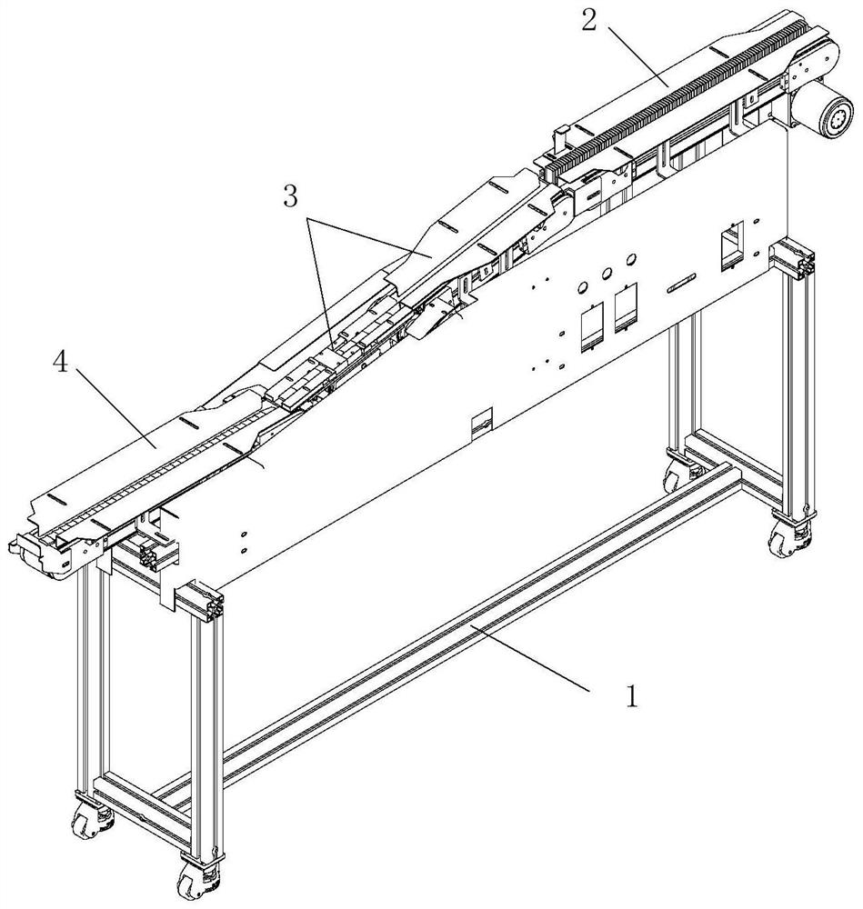
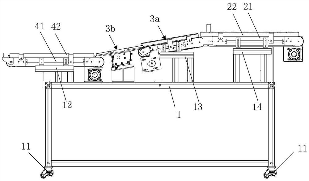
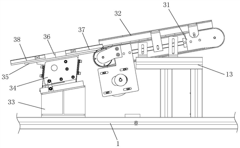
[0023] Combine references Figures 1 to 4 , the ferrite magnetic tile pass gauge detection line of the present invention comprises a rack 1, a magnetic pad feeding device 2, a pass gauge device 3, and a magnetic pad receiving device 4.
[0024] Rack 1 is an aluminum profile frame construction with horizontally adjustable castors 11 mounted at all four corners, such as the GD-40F, capable of moving position and leveling. There are also three aluminum profile structural brackets 12, 13 and 14 on rack 1.
[0025] The magnetic tile feeding device 2 is supported on the frame 1, consisting of a first belt conveyor 21, a magnetic tile groove 22 disposed on its conveyor surface, an extension plate 23 located at the end of the conveying surface.
[0026] The magnetic tile groove 22 is composed of a left baffle 221 and a right baffle 222, the position of the left baffle and the right baffle can be adjusted each to form a different width of the slot, adapting to different widths of the magnetic pad. The conveying speed of the first belt conveyor 21 is a medium and high speed conveyor, the conveying speed is 0.3m /s-0.8m /s. For example, the total length of the first belt conveyor 21 is about 65cm.
[0027] Magnetic tile feeding device 2 has two ways to use, one is connected to the outlet of the magnetic tile cleaning machine, receiving the collapsed magnetic tile; the other is to directly place the magnetic tiles in an upright column, which is used for magnetic tile packaging occasions, allowing more number of magnetic tiles to be placed in the unit length, and 100% of the product is fully inspected.
[0028] The pass gauge device 3 is connected by two parts of the magnetic tile push unit 3a and the direct vibration pass gauge unit 3b, which is the core component of the detection line.
[0029]Magnetic tile push unit 3a is composed of a second belt conveyor 31 and a magnetic tile trough 32 located on its conveyor surface, the conveying speed of the second belt conveyor is greater than that of the first belt conveyor, and the starting end of the straight conveyor surface of the second belt conveyor has a drop with the extension plate, for example, 1cm-2cm.
[0030] The above design layout allows the upright rows of end tiles to be independently lodging in turn on the straight conveyor surface of the second belt conveyor. And when the magnetic tile in the first belt conveyor is in the groove of the magnetic tile is in the lodging state (such as the magnetic tile sent by the upstream washing machine), it will still remain lodging when it reaches the conveyor surface of the second belt conveyor.
[0031] Independent lodging here means that there is no lap relationship between the front and rear magnetic tiles, and the rear end of the front magnetic tile is in conflict or space with the front end of the rear magnetic tile.
[0032] Direct vibration over the pass gauge unit 3b is arranged at a small inclination (0 °, 30 °], for example, it includes a base 33, a direct oscillator 34, located on the top of the direct oscillator and driven by a direct oscillator top plate 35, a pass gauge gage 36 disposed on the top plate and an upstream magnetic tile trough 37 and a downstream magnetic tile 38 located upstream and downstream of the pass gauge gage.
[0033] Upstream magnetic tile guide 37 and the end of the straight conveyor surface of the second belt conveyor 31 is connected, the magnetic tile push unit 3a and the direct vibration pass gauge unit 3b are preferably inclined coplanar arrangement.
[0034] The gauge gage 36 is composed of a guide groove 361, a guide tile surface 362 adapted to a standard magnetic tile, and a gage body 363, wherein the gage body has a gauge hole 364.
[0035] The second belt conveyor makes the magnetic tiles clustered one by one in front of the gauge holes of the gauge gauge and has a certain forward thrust. The small inclination configuration of the direct oscillator is used to provide the vibration force, allowing the end of the magnetic tile to smoothly enter the through gauge hole.
[0036] The magnetic tile receiving device 4 is disposed on the frame 1, consisting of a third belt conveyor 41, a magnetic tile groove 42 located on its conveyor surface and an ebander 43 located at the end of the magnetic tile groove 43. For example, the total length of the third belt conveyor 21 is about 55cm.
[0037] The conveying speed of the third belt conveyor is adjusted to meet the satisfaction: in the magnetic tile groove, the latter magnetic tile is inverted and overlapped on the previous magnetic tile, showing an inverted lap relationship to facilitate tile collection.
[0038] The tile collection operation is as follows: the magnetic tile at the end of the conveying surface is pulled up and gathered forward, so that the magnetic tiles in the groove can be erected in a column, so that it is convenient for storage and packaging.
[0039] as Figure 5As shown, the detection line of the present invention further comprises a magnetic tile scribing device 5 for scribing the magnetic tiles moving through the groove of the first magnetic tile, comprising a scribing bracket 51, an elastic connector 52, and a scribing pen 53. The elastic connector may be a steel wire, so that the scriber may float on the top surface of the upright magnetic tile 30 or the curved back of the inverted magnetic tile, as a process marking.
[0040] as Figure 6 As shown, the detection line of the present invention is arranged in a two-wire body, comprising a first wire body 10 and a second wire body 20 disposed on the rack 1, both of which have the same structure, in Figure 6 The magnetic tile receiving device is not shown, and the two-wire body shares a third belt conveyor. Further, the magnetic pad push unit 3a of the transmission surface and the direct vibration through the gauge unit 3b of the roof surface is relatively deflected, such as an angle of about 170 °, so that in the face of a large size of the magnetic tile still retains the effect of pushing the magnetic pad forward.
[0041] The detection line of the present invention also provides an automatic shutdown function when stopping, i.e., the first sensor 61 and a second sensor 62 are arranged before and after the pass gauge gage, such as a photoelectric sensor, the first sensor and the second sensor are triggered when the magnetic tile is detected, the stopper shutdown condition is: if the first sensor detects the magnetic tile and delays the setting time after the second sensor is not triggered, the shutdown is triggered. Then, by manual intervention, the plug is cleaned.
[0042] The following takes the packaging occasion as an example of the working process of the detection line of the present invention is described.
[0043] First, the upright magnetic tile is placed in the magnetic tile groove of the magnetic tile feeding device, and then the magnetic tile moves along the linear body, changes from the upright attitude to the lodging attitude, and passes the gauge detection under the action of direct vibration and thrust, and finally reaches the magnetic tile groove of the magnetic tile collection device, and then the manual or manipulator will dial the end magnetic tile and gather it forward to the upright column state, and then the upright column magnetic tile is removed and packaged as a whole. When the stopper is stopped and the stopper tile is determined to be unqualified, the detection work continues after the tile is removed.
[0044] The above is only a preferred embodiment of the present invention only, and is not intended to limit the present invention, for those skilled in the art, the present invention may have various changes and variations. Any modifications, equivalent substitutions, improvements, etc. made within the spirit and principles of the present invention shall be included within the scope of the invention.

PUM

no PUM

Description & Claims & Application Information

We can also present the details of the Description, Claims and Application information to help users get a comprehensive understanding of the technical details of the patent, such as background art, summary of invention, brief description of drawings, description of embodiments, and other original content. On the other hand, users can also determine the specific scope of protection of the technology through the list of claims; as well as understand the changes in the life cycle of the technology with the presentation of the patent timeline. Login to view more.

Similar technology patents

Energy consumption data acquisition unit

InactiveCN105572469AVersatileStrong compatibility
Owner:SUZHOU IND PRAK NEW HONGBO COMM TECH

Automatic window closing machine used on rainy days

InactiveCN107448090AStrong compatibilitySpeed ​​up the closing time
Owner:丁玉清

Multi-rotor unmanned aerial vehicle hangar

ActiveCN114212265AAvoid damage or damage problemsStrong compatibility
Owner:蜂巢航宇科技(北京)有限公司

DIY type all-in-one touch screen remote controller

InactiveCN102708673AStrong compatibility
Owner:国网重庆云阳县供电有限责任公司

Classification and recommendation of technical efficacy words

  • Strong compatibility
  • low cost

Parking guidance system based on cloud platform and AGPS (Assisted Global Positioning System)

InactiveCN103226896APrecise Parking Guidance ServiceStrong compatibility
Owner:KUNMING DABANGKE SCI & TECH CO LTD

Method for video playing and based on stream media system

InactiveCN102387409AConvenient network scaleStrong compatibility
Owner:JIANGSU YUANWEI TECH

Method for leading out Word under BS system

Owner:ANHUI SUN CREATE ELECTRONICS

System and method for transmitting wireless digital service signals via power transmission lines

ActiveUS7929940B1reduce bandwidth requirementlow cost
Owner:NEXTEL COMMUNICATIONS

System and method for determination of position

InactiveUS20090149202A1low costreduce requirement
Owner:STEELE CHRISTIAN

Adaptive antenna optimization network

InactiveUS6961368B2low costminimal space
Owner:ERICSSON INC

Antenna device and method for attaching the same

ActiveUS20150138022A1low costimproved strength characteristic
Owner:NEC CORP
Why Eureka
Try Eureka