Supercharge Your Innovation With Domain-Expert AI Agents!

High-performance lock riveting rivet for automobile and press riveting upper die of high-performance lock riveting rivet

A high-performance, locking riveting technology, applied in the direction of rivets, screws, connecting components, etc., can solve the problems that the locking rivets cannot be fully fitted, it is difficult to achieve anti-rotation effect, and the air tightness is poor. The effect of enhanced capacity and improved riveting performance

Pending Publication Date: 2022-05-27
厦门同恒金属有限公司
View PDF0 Cites 0 Cited by
  • Summary
  • Abstract
  • Description
  • Claims
  • Application Information

AI Technical Summary

Problems solved by technology

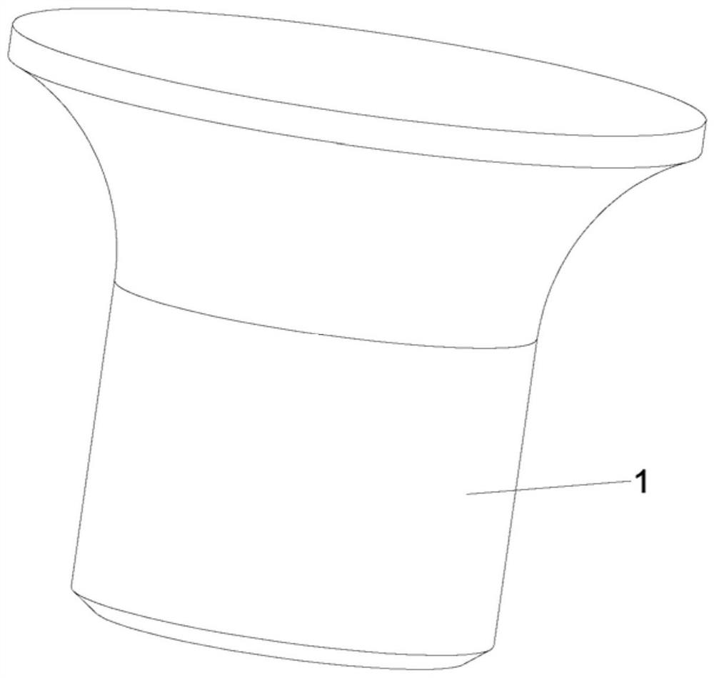
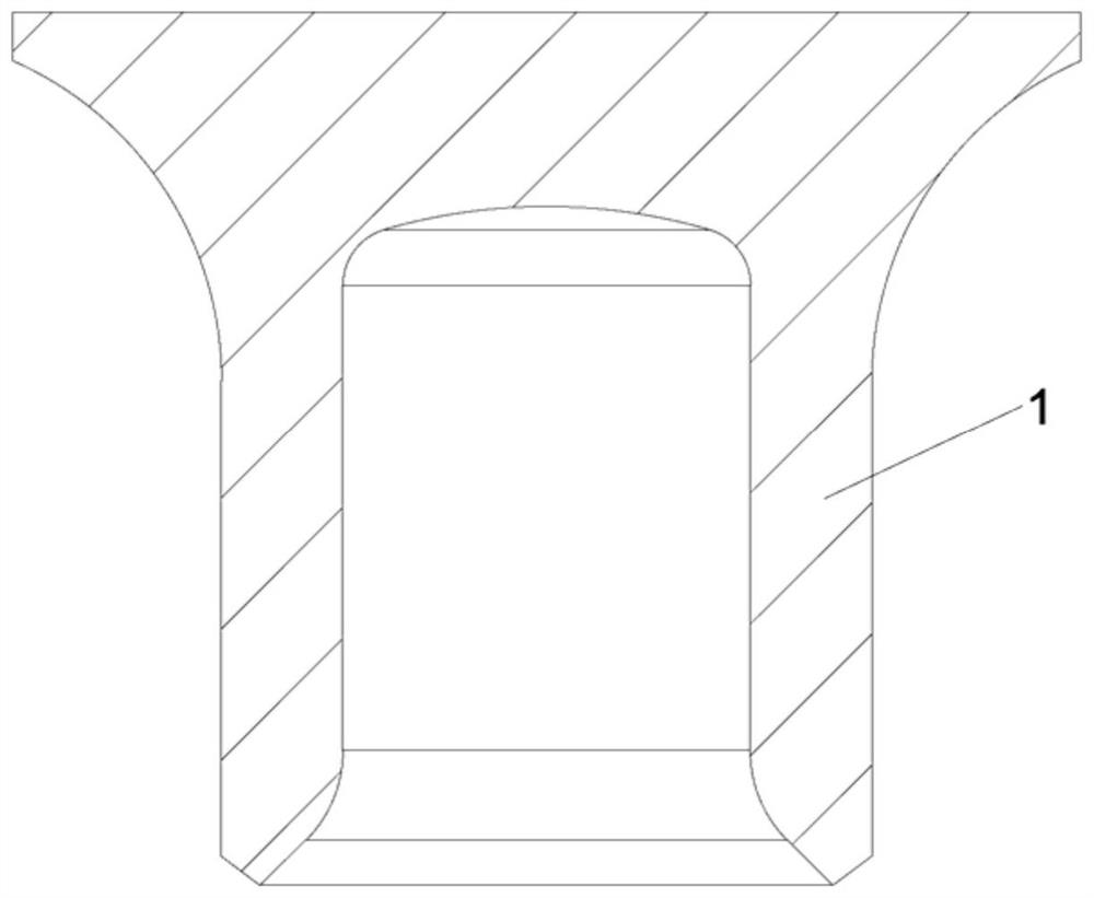
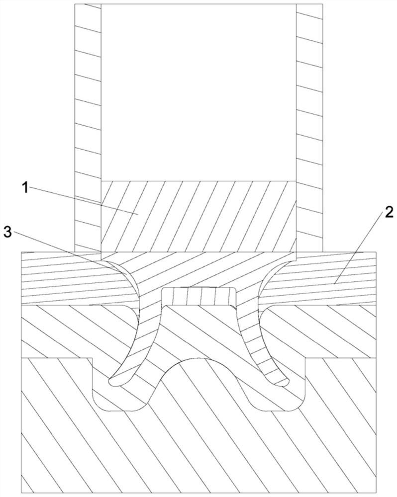
[0004] At present, common lock rivets such as Figures 1 to 3 As shown, after riveting, it is impossible to ensure that the lock rivet 1 and the plate 2 are completely attached, the gap 3 between the lock rivet 1 and the plate 2 is large, and the airtightness is poor; only relying on the radial friction between the lock rivet 1 and the plate 2 Force provides torque, it is difficult to achieve effective anti-rotation effect

Method used


Image

  • High-performance lock riveting rivet for automobile and press riveting upper die of high-performance lock riveting rivet
  • High-performance lock riveting rivet for automobile and press riveting upper die of high-performance lock riveting rivet
  • High-performance lock riveting rivet for automobile and press riveting upper die of high-performance lock riveting rivet

Examples


Embodiment Construction

[0041] In order to solve the technical problems, technical solutions and beneficial effects of the present invention to be more clear and understandable, the following in conjunction with the accompanying drawings and embodiments, the present invention will be further elaborated in detail. It should be understood that the specific embodiments described herein are only used to explain the present invention and are not intended to qualify the present invention.

[0042] The claims of the present invention, the description and the above-mentioned drawings, unless otherwise expressly qualified, such as the use of the terms "first", "second" or "third", etc., are intended to distinguish different objects, rather than to describe a particular order.

[0043]In the claims of the present invention, the specification and the above-mentioned drawings, unless otherwise expressly defined, for azimuth words, such as the use of the terms "center", "horizontal", "vertical", "vertical", "top", "b...


PUM

PropertyMeasurementUnit
Diameteraaaaaaaaaa

Abstract

According to the high-performance lock riveting rivet for the automobile and the press riveting upper die of the high-performance lock riveting rivet, an inner arc part is formed by a head part and a rivet leg part, and an annular groove is formed in the top end face of the head part in a downward concave mode so that a riveting deformation corner can be formed. A plurality of cut edges are uniformly distributed on the outer wall of the nail leg part; and an inner hole is formed. The inner hole is composed of an upper straight hole part and a lower chambering part. The hole wall of the lower reaming part is of a multi-step structure formed by sequentially connecting a first chamfering part, a first conical surface, a second conical surface, a second chamfering part and a third chamfering part, so that a nail leg tip part is formed at the bottom of the nail leg part; the first conical surface of the lower chambering part is connected with the hole wall of the upper straight hole part through a first chamfering part; the second conical surface is connected with a third chamfer part through a second chamfer part, and the third chamfer part is connected with the outer wall of the nail leg part. The pressing rivet upper die is annularly provided with a slope portion. The riveted lock riveting rivet can be completely attached to the plate, the gap is small, larger pulling-out force can be borne, and the air tightness is good; the anti-rotation device has effective anti-rotation measures and a certain anti-rotation effect, can be formed at a time, and is low in cost.

Description

Technical field [0001] The present invention belongs to the field of fastener manufacturing technology, specifically relates to an automotive high-performance lock rivet and its press rivet upper die. Background [0002] Fasteners are a type of mechanical parts that are used for fastening and connection and are widely used. In all kinds of machinery, equipment, vehicles, ships, railways, bridges, buildings, structures, tools, instruments, meters and supplies, you can see a variety of fasteners. [0003] Riveting in the vehicle fastener is a prefabricated hole in the riveted part of the lock rivet through the riveting part, so that two or more riveted parts are connected together, so that the undoneable connection is constituted. Riveting has the advantages of simple process equipment, seismic resistance, impact resistance and firm and reliable. The riveting points of the traditional riveting process are prone to friction and noise and quality defects, resulting in loosening, caus...

Claims


Application Information

Patent Timeline
IPC IPC(8): B21J15/02F16B19/08
CPCB21J15/025F16B19/086
Inventor 苏标庚李学宽程俊琪兰华兴张晓琳
Owner 厦门同恒金属有限公司
Features
  • R&D
  • Intellectual Property
  • Life Sciences
  • Materials
  • Tech Scout
  • Unparalleled Data Quality
  • Higher Quality Content
  • 60% Fewer Hallucinations
Learn More