Supercharge Your Innovation With Domain-Expert AI Agents!

Composite splicing riveting tooling for electrical cabinets

An electric cabinet and riveting technology, which is applied in the field of electrical box splicing, can solve the problems of waste of manpower, low work efficiency, and unsightly electrical box frame, so as to increase the riveting effect, improve applicability, and facilitate riveting operations Effect

Active Publication Date: 2020-11-20
JIANGSU ELECTRIC POWER CO
View PDF5 Cites 0 Cited by
  • Summary
  • Abstract
  • Description
  • Claims
  • Application Information

AI Technical Summary

Problems solved by technology

[0003] When the existing electrical box frame is produced, multiple workers are often used to operate the splicing and riveting between the electrical frames. One worker clamps and rives the electrical frame with both hands, and the other worker performs the riveting operation. This method is a waste of manpower and low work efficiency, and when the electrical frame is riveted and clamped manually, the parallelism and verticality of the electrical frame cannot be guaranteed, resulting in an unsightly appearance of the electrical box frame after forming and easily affecting the use

Method used


Image

  • Composite splicing riveting tooling for electrical cabinets
  • Composite splicing riveting tooling for electrical cabinets
  • Composite splicing riveting tooling for electrical cabinets

Examples


Embodiment Construction

[0022] In order to make the technical means, creative features, goals and effects achieved by the present invention easy to understand, the present invention will be further described below in conjunction with specific illustrations. It should be noted that, in the case of no conflict, the embodiments in the present application and the features in the embodiments can be combined with each other.

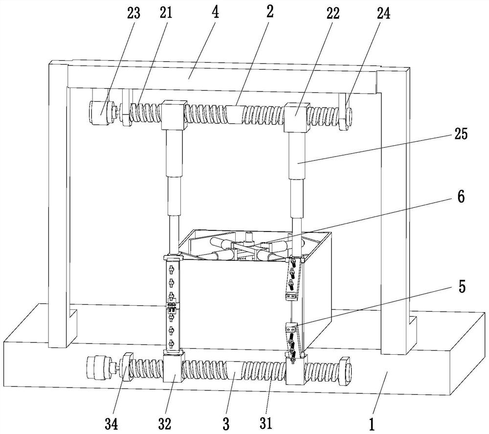
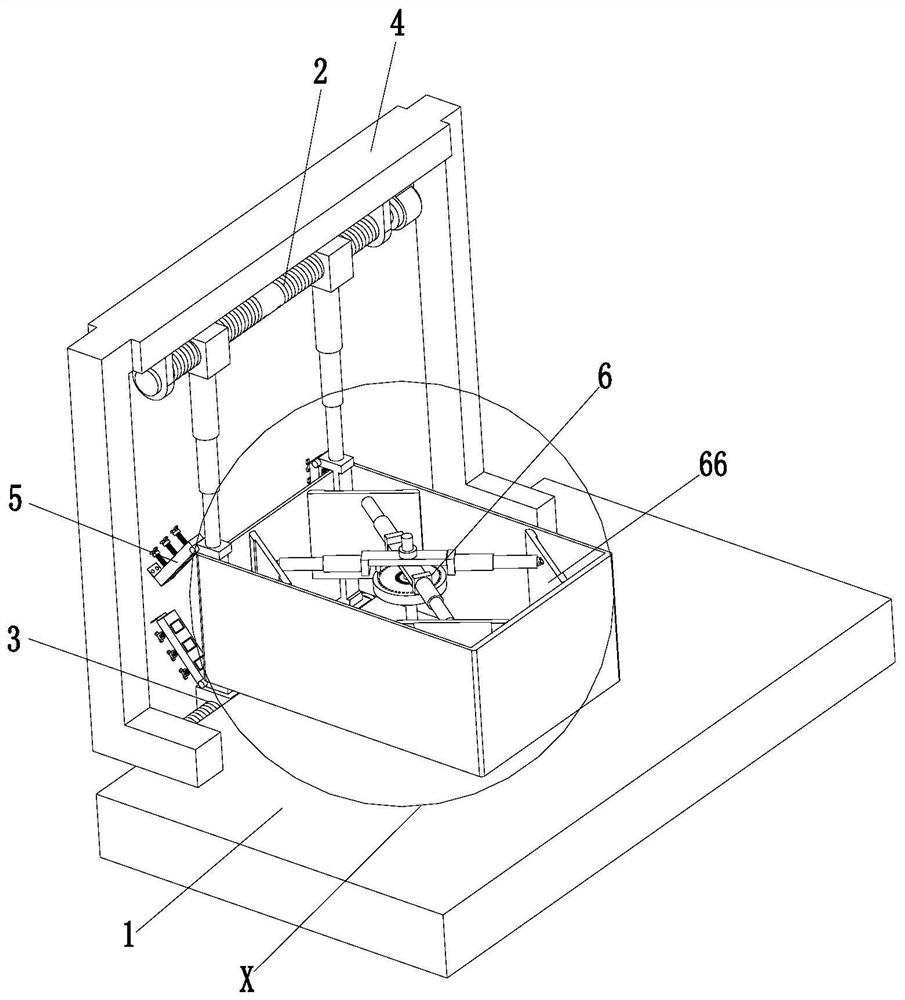
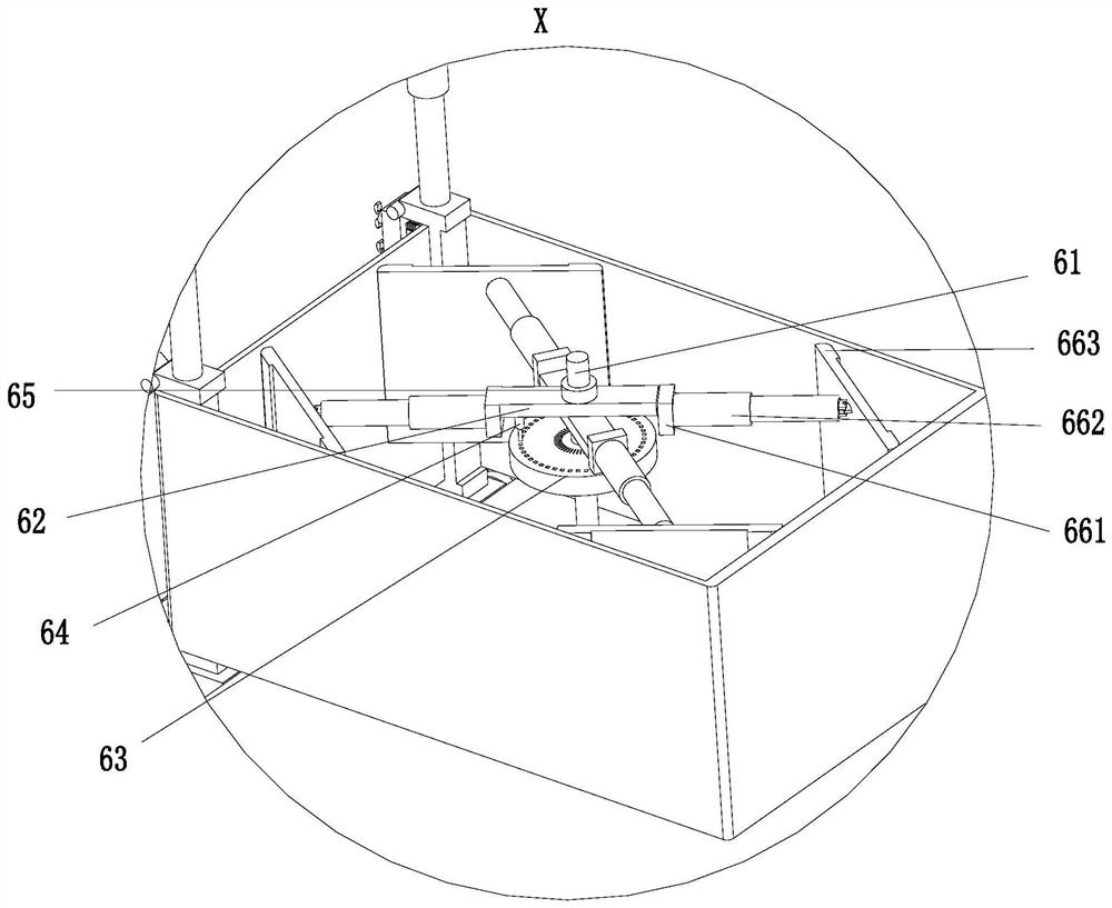
[0023] like Figure 1 to Figure 4 As shown, a compound splicing riveting tool for electrical cabinets, including a bottom plate 1, an upper moving mechanism 2, a lower moving mechanism 3, a suspension beam 4, a riveting mechanism 5 and an inner support device 6, above the bottom plate 1 is provided with Suspension beam 4, the left and right ends of suspension beam 4 are installed on the top front side of base plate 1 by bracket, upper moving mechanism 2 is positioned at the below of suspension beam 4, and the top of upper movement mechanism 2 is installed on the bottom of suspension ...


PUM


Abstract

The invention relates to a composite splicing and riveting tool for an electrical box cabinet. The composite splicing and riveting tool comprises a bottom plate, an upper moving mechanism, a lower moving mechanism, a suspending beam, riveting mechanisms and an inner supporting device, wherein the suspending beam is arranged above the bottom plate; the top of the upper moving mechanism is mounted on the bottom of the suspending beam; the lower moving mechanism is positioned at the front side of the bottom plate; the rear end of the lower moving mechanism is mounted on the front side surface ofthe bottom plate; one group of riveting mechanisms is symmetrically arranged below the upper moving mechanism left and right; each group of riveting mechanisms comprises two riveting mechanisms, the top of one riveting mechanism is mounted on the bottom of the upper moving mechanism, the bottom of the other riveting mechanism is mounted on the top of the lower moving mechanism, and the bottom of the inner supporting device is mounted at the top end of the bottom plate. The composite splicing and riveting tool can solve the problems that the electrical box frame body is not attractive and evenaffects use, and the like as manual riveting and clamping for an electrical frame body greatly wastes labor power, is low in working efficiency, and cannot guarantee parallelism degree and perpendicularity of the electrical frame body.

Description

technical field [0001] The invention relates to the technical field of electric box splicing, in particular to a riveting tool for composite splicing of electric boxes and cabinets. Background technique [0002] The distribution box of the electrical box has the characteristics of small size, easy installation, special technical performance, fixed position, unique configuration function, not limited by the site, common application, stable and reliable operation, high space utilization rate, less land occupation and environmental protection effect . Commonly used distribution boxes are made of wood and metal. Because the protection level of metal distribution boxes is higher, metal is still used more. There are two types of distribution box structures, welding structure: simply cut, bend, open holes and weld the sheet metal parts. Assembled structure: the sheet metal parts are processed separately, each part is assembled after processing, reinforced and locked with screws a...

Claims


Application Information

Patent Timeline
Patent Type & Authority Patents(China)
IPC IPC(8): B21J15/14B21J15/38B21J15/42
CPCB21J15/14B21J15/38B21J15/42
Inventor 李美冬伍勇军夏可欣
Owner JIANGSU ELECTRIC POWER CO
Features
  • R&D
  • Intellectual Property
  • Life Sciences
  • Materials
  • Tech Scout
  • Unparalleled Data Quality
  • Higher Quality Content
  • 60% Fewer Hallucinations
Learn More