Supercharge Your Innovation With Domain-Expert AI Agents!

Automatic assembly machine for iron core assembly

An assembly machine and component technology, applied in the direction of feeding device, storage device, positioning device, etc., can solve the problems of easy bending shaft, bending shaft part, affecting assembly quality, etc., to reduce labor intensity and prevent circumferential deviation The effect of moving and improving assembly efficiency and quality

Pending Publication Date: 2018-01-09
CHONGQING LINGLONG AUTOMATION EQUIP CO LTD
View PDF0 Cites 12 Cited by
  • Summary
  • Abstract
  • Description
  • Claims
  • Application Information

AI Technical Summary

Problems solved by technology

[0003] 1. The feeding and straightening of the iron cores are mostly carried out manually, that is, the operator adjusts the circumferential position of each iron core and places them in each iron core positioning structure one by one; the feeding and straightening of the commutator components are mostly It is through manual operation, that is, the operator adjusts the circumferential position of each commutator assembly and then transfers them to the next station one by one. This will not only increase the labor intensity of the operator, but also greatly affect the assembly. efficiency
[0004] 2. Lack of positioning structure for the commutator assembly, it is easy to bend the shaft during riveting; lack of positioning structure for the iron core, the iron core is prone to circumferential deviation during riveting
Since the iron core and commutator components are relatively fine parts, if the iron core and commutator components are not well positioned, there is a high possibility of defective products.
[0005] 3. When the riveted iron core assembly is being unloaded, the operator can only hold the commutator assembly to remove the finished product. In this way, it is easy to bend the shaft and affect the assembly quality

Method used


Image

  • Automatic assembly machine for iron core assembly
  • Automatic assembly machine for iron core assembly
  • Automatic assembly machine for iron core assembly

Examples


Embodiment 1

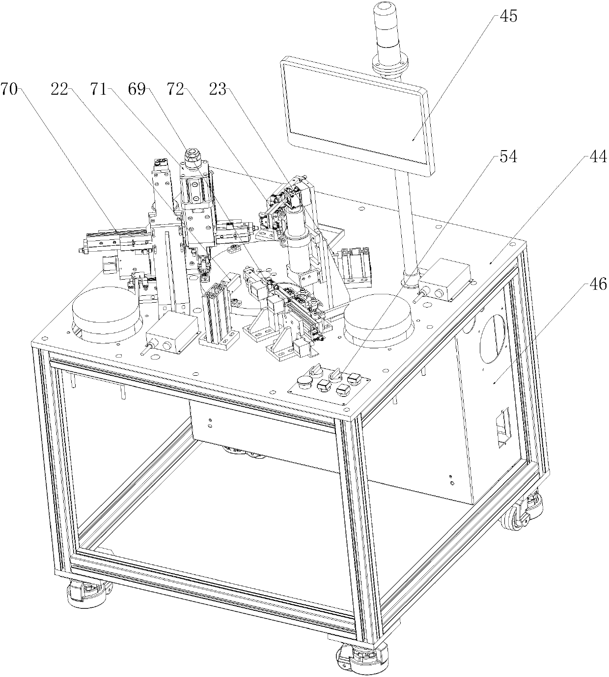
[0075] like Figure 1 to Figure 19 As shown, an automatic assembly machine for iron core components, including a turntable component and an iron core feeding and straightening component, a commutator component feeding and straightening component, a riveting component and a blanking component that are sequentially arranged along the rotation direction of the turntable component;

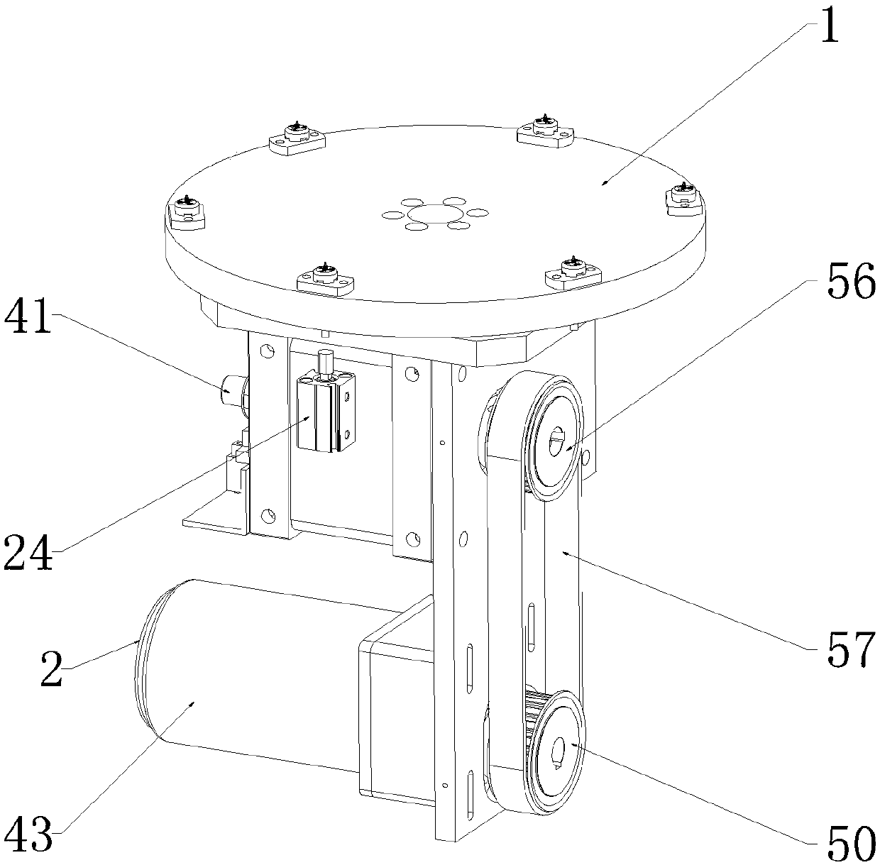
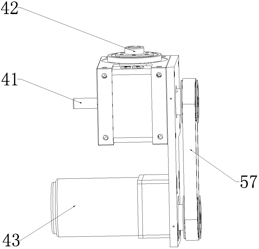
[0076] The turntable assembly includes a turntable 1 and a first drive device 2 for driving the turntable 1 to rotate, and the turntable 1 is provided with several circularly arranged positioning seat assemblies;

[0077]The iron core feeding and correcting assembly includes an iron core correcting part and a suction nozzle transfer part, and the iron core correcting part includes a first straightening table 6, a first image collector 7 located above the first straightening table 6 and a device for driving the first straightening table. 6 The second driving device 8 that rotates, the nozzle transfer p...

Embodiment 2

[0085] This embodiment makes the following further limitations on the basis of Embodiment 1: the positioning seat assembly includes a positioning seat 3, and the positioning seat 3 is provided with a concave positioning groove 4, and the positioning seat 3 is also provided with several circular arrays. And the limiting protrusion 5 extending toward the middle of the positioning groove 4 .

[0086] In this embodiment, for the convenience of processing, several stoppers 65 can be set on the positioning seat 3, the number of stoppers 65 is consistent with the number of iron core winding grooves, and each stopper 65 has the said limiting protrusion part 5 , and the area surrounded by a plurality of blocking pieces 65 forms the positioning groove 4 .

Embodiment 3

[0088] This embodiment makes the following further limitations on the basis of Embodiment 2: the middle part of the positioning seat 3 is provided with a first through hole 27 passing through its upper and lower end surfaces and communicating with the positioning groove 4;

[0089] The positioning seat assembly also includes a hollow supporting base 25, the supporting base 25 is connected to the lower end of the positioning seat 3;

[0090] The top end of the support base 25 is provided with a second through hole 49 communicating with its inner cavity;

[0091] The inner cavity of the support base 25 is provided with a push rod 26 through the second elastic member 72, the lower end of the push rod 26 runs through the bottom end of the support base 25, and the push rod 26 can move upward relative to the support base 25;

[0092] It also includes an eighth driving device 24 arranged below the turntable 1 , the eighth driving device 24 can act on the push rod 26 to move up and pu...


PUM


Abstract

The invention discloses an automatic assembly machine for an iron core assembly. The automatic assembly machine for the iron core assembly comprises a rotating disk assembly, an iron core feeding straightening assembly, a reverser assembly feeding straightening assembly, a riveting pressure assembly and a discharging assembly, and the iron core feeding straightening assembly, the reverser assemblyfeeding straightening assembly, the riveting pressure assembly and the discharging assembly are sequentially arranged in the rotating direction of the rotating disk assembly; the rotating disk assembly comprises a rotating disk and a first driving device; the iron core feeding straightening assembly comprises an iron core straightening part and a sucking nozzle transferring part; the reverser assembly feeding straightening assembly comprises a reverser assembly straightening part; the riveting pressure assembly comprises a riveting pressure part and a positioning part; and the discharging assembly comprises a second clamping device and a seventh driving device used for driving the second clamping device to move. In the automatic assembly machine for the iron core assembly, under the driving of the rotating disk, a plurality of positioning base assemblies are circulated between various stations to form a smooth iron core assembly production line, in this way, the labor intensity of operators can be reduced, and the assembling efficiency and quality of the iron core assembly can also be greatly improved.

Description

technical field [0001] The invention relates to the technical field of iron core assembly assembly, in particular to an automatic assembly machine for iron core assemblies. Background technique [0002] The assembly work of the iron core assembly refers to: the iron core is riveted on the shaft of the commutator assembly, and the winding groove of the iron core is facing the hanging wire piece of the commutator. In the existing assembly process, the loading of iron core or commutator components and the unloading of finished products are mostly carried out manually, which has the following problems: [0003] 1. The feeding and correction of the iron cores are mostly carried out manually, that is, the operator adjusts the circumferential position of each iron core and places them in each iron core positioning structure one by one; the feeding and correction of the commutator components are mostly It is through manual operation, that is, the operator adjusts the circumferentia...

Claims


Application Information

Patent Timeline
IPC IPC(8): B23P19/02B21D43/18
Inventor 朱昌国汪涛李伟铨
Owner CHONGQING LINGLONG AUTOMATION EQUIP CO LTD
Features
  • R&D
  • Intellectual Property
  • Life Sciences
  • Materials
  • Tech Scout
  • Unparalleled Data Quality
  • Higher Quality Content
  • 60% Fewer Hallucinations
Learn More