Bearing seat multi-station machining device convenient to fix
A processing device and multi-station technology, applied in the direction of positioning devices, metal processing equipment, metal processing machinery parts, etc., can solve problems such as unfavorable production, trouble, unstable clamping of bearing seats, etc., to achieve improved clamping effect, The structure of the device is simple, and the effect of increasing the positioning effect
- Summary
- Abstract
- Description
- Claims
- Application Information
AI Technical Summary
Problems solved by technology
Method used
Image

Examples
Embodiment 1
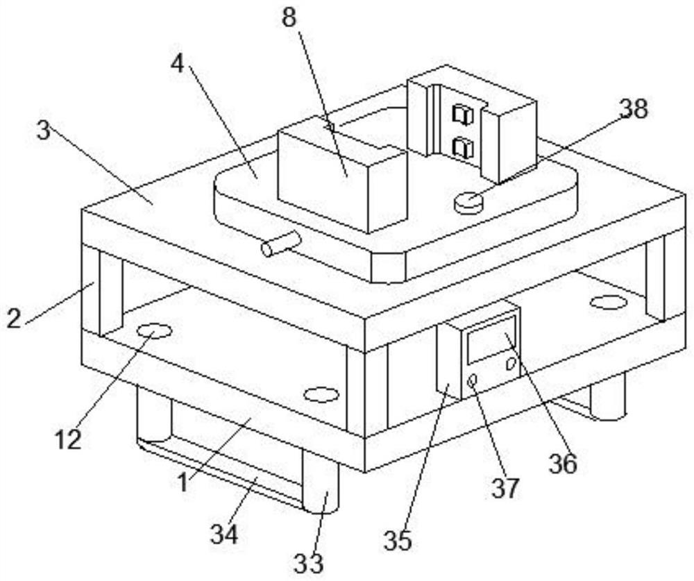
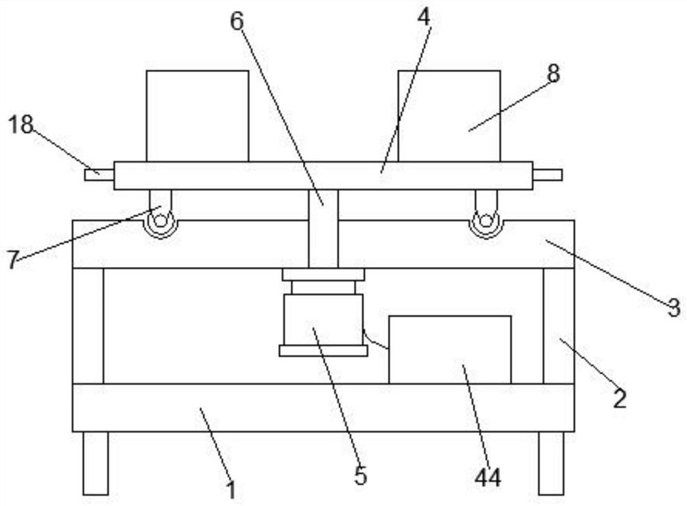
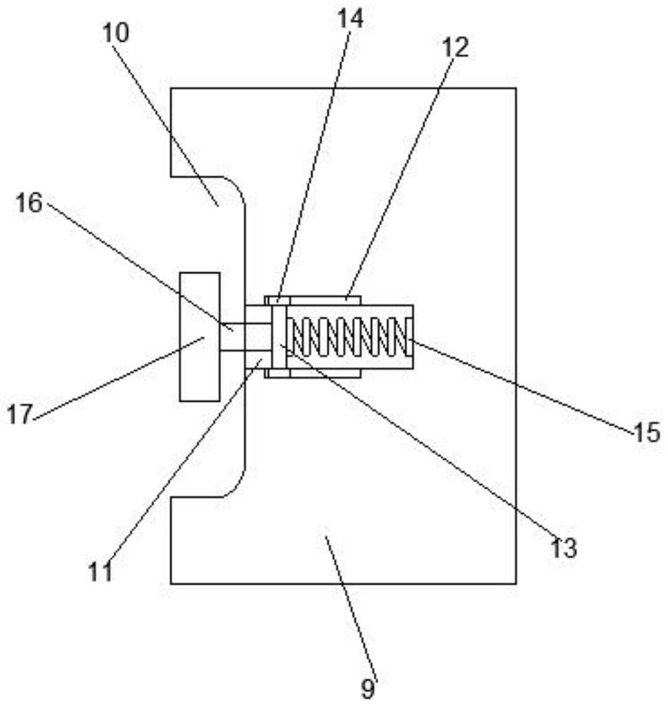
[0029] see Figure 1-6 , according to an embodiment of the present invention, a bearing seat multi-position processing device that is easy to fix includes a fixed base plate 1, and a support base plate 3 is installed on the fixed base plate 1 through four support rods 2, and a support base plate 3 is arranged above the support base plate 3 There is a rotating table 4, a drive motor 5 is fixed at the bottom center of the support base plate 3, and a transmission rod 6 is provided at the output end of the drive motor 5, and the transmission rod 6 penetrates through the support base plate 3 and the A rotating worktable 4 is connected, an auxiliary rotating structure 7 is symmetrically arranged between the rotating worktable 4 and the supporting base plate 3, and a positioning and clamping structure 8 is symmetrically arranged on the rotating worktable 4. The positioning and clamping structure 8 includes a side splint 9, an arc-shaped slot 10 is opened on the side splint 9, an inst...
Embodiment 2
[0032] like figure 1 As shown, a support base plate 3 is installed on the fixed base plate 1 through four support rods 2, a rotating table 4 is arranged above the support base plate 3, and a drive motor 5 is fixed at the bottom center of the support base plate 3, The output end of the drive motor 5 is provided with a transmission rod 6 , and the transmission rod 6 penetrates through the supporting base plate 3 and is connected to the rotating worktable 4 , and is symmetrically arranged between the rotating worktable 4 and the supporting baseplate 3 . There is an auxiliary rotating structure 7, and a positioning and clamping structure 8 is symmetrically arranged on the rotating table 4. The positioning and clamping structure 8 includes a side clamp plate 9, and an arc-shaped slot 10 is opened on the side clamp plate 9. The side splint 9 is provided with an installation and positioning groove 11 , the inner wall of the installation and positioning groove 11 is symmetrically prov...
Embodiment 3
[0034] like figure 1 As shown, a support base plate 3 is installed on the fixed base plate 1 through four support rods 2, a rotating table 4 is arranged above the support base plate 3, and a drive motor 5 is fixed at the bottom center of the support base plate 3, The output end of the drive motor 5 is provided with a transmission rod 6 , and the transmission rod 6 penetrates through the supporting base plate 3 and is connected to the rotating worktable 4 , and is symmetrically arranged between the rotating worktable 4 and the supporting baseplate 3 . There is an auxiliary rotating structure 7, and a positioning and clamping structure 8 is symmetrically arranged on the rotating table 4. The positioning and clamping structure 8 includes a side clamp plate 9, and an arc-shaped slot 10 is opened on the side clamp plate 9. The side splint 9 is provided with an installation and positioning groove 11 , the inner wall of the installation and positioning groove 11 is symmetrically prov...
PUM
 Abstract
Description
Claims
Application Information
 - Generate Ideas
- Intellectual Property
- Life Sciences
- Materials
- Tech Scout
- Unparalleled Data Quality
- Higher Quality Content
- 60% Fewer Hallucinations
Browse by: Latest US Patents, China's latest patents, Technical Efficacy Thesaurus, Application Domain, Technology Topic, Popular Technical Reports.
© 2025 PatSnap. All rights reserved.Legal|Privacy policy|Modern Slavery Act Transparency Statement|Sitemap|About US| Contact US: help@patsnap.com