Column-filling ink device

An ink and column filling technology, applied in printing and other directions, can solve problems such as drying, waste, and ink adhesion to the inner cavity wall, and achieve the effects of increasing volume, easy operation, and ingenious structural design.

Pending Publication Date: 2022-05-27
王丹
View PDF1 Cites 0 Cited by
  • Summary
  • Abstract
  • Description
  • Claims
  • Application Information

AI Technical Summary

Problems solved by technology

[0003] For example, a Chinese patent with application number CN201220403816.5 discloses a multi-stage ink filling device comprising an auxiliary ink supply chamber, a main ink supply chamber located below the auxiliary ink supply chamber, a slideway arranged in the main ink supply chamber, and a slideway arranged in the main ink supply chamber. The piston on the slide and matched with it, and the ink ejection port arranged at the lower end of the main ink supply chamber, etc., have utilized the upper and lower two-stage ink supply chambers to increase the storage capacity of ink, but due to the large number of ink chambers As a result, in winter or when it has not been used for a long time, part of the ink remaining in the room will adhere to the wall of the inner cavity, dry and difficult to fall off over time, resulting in waste

Method used


Image

  • Column-filling ink device
  • Column-filling ink device
  • Column-filling ink device

Examples


Embodiment Construction

[0022] The technical solutions of the patent of the present invention will be clearly and completely described below with reference to the accompanying drawings. Obviously, the described embodiments are a part of the embodiments of the present invention, but not all of the embodiments. Based on the embodiments of the present invention, all other embodiments obtained by those skilled in the art without creative efforts shall fall within the protection scope of the present invention.

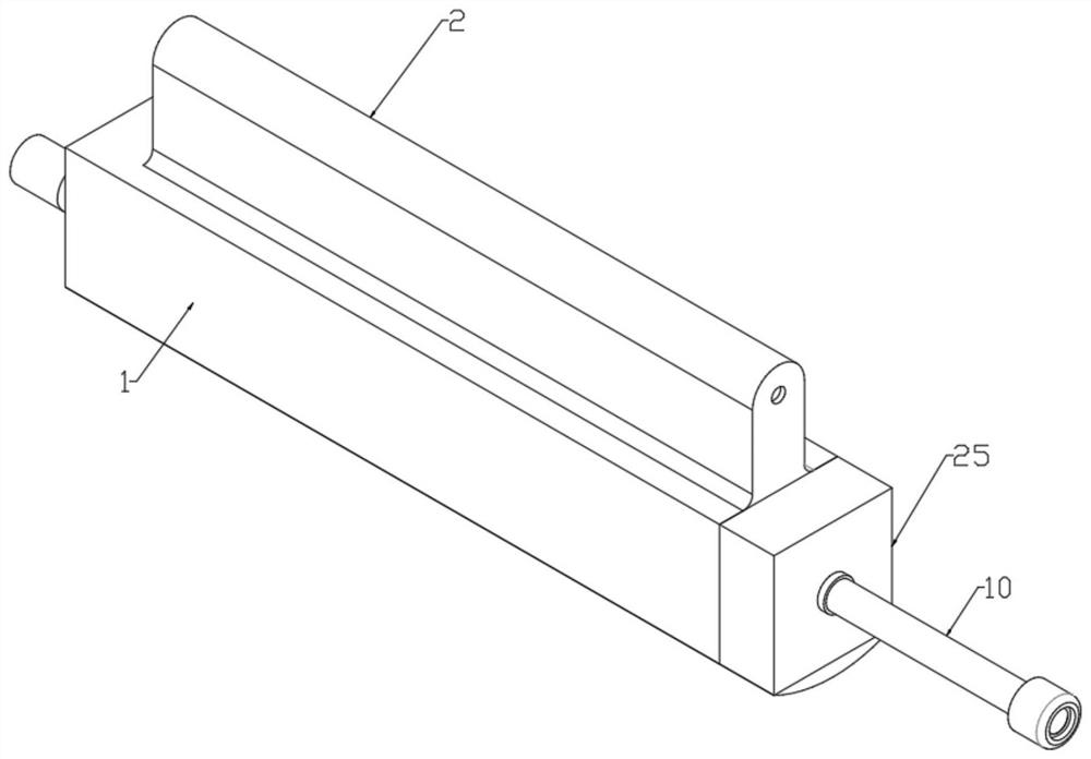
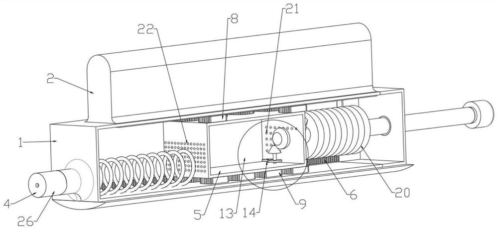
[0023] like Figure 1 to Figure 6 shown.

[0024] The ink filling device provided in this embodiment includes a primary ink tank 1 and a secondary ink tank 2 arranged on the top of the primary ink tank 1. A space is opened between the primary ink tank 1 and the secondary ink tank 2 for a The ink in the primary ink tank 1 is replenished to the discharge hole 3 in the secondary ink tank 2. When the ink in the primary ink tank 1 is less and the secondary ink tank 2 contains ink, the ink in the secon...


PUM


Abstract

The invention provides a column ink filling device, relates to the technical field of ink filling devices, solves the problem of ink waste, and comprises a first-stage ink cabin and a second-stage ink cabin arranged at the top of the first-stage ink cabin, and a discharge hole used for supplementing ink in the first-stage ink cabin into the second-stage ink cabin is formed between the first-stage ink cabin and the second-stage ink cabin; the discharging pipe is located at the liquid outlet end of the first-stage ink chamber and provided with a valve, the pressing seat is located in a box cavity of the first-stage ink chamber, pushed towards the discharging pipe and used for discharging ink from the discharging pipe, friction is formed between gears and the chamber wall when the gears rotate, and the chamber wall is heated through friction; therefore, the printing ink changed into a semi-fluid state due to precipitation in the cabins is heated and diluted, so that the printing ink is smoothly discharged, the utilization rate is improved, the loss is reduced, the gears are divided into an upper group and a lower group and act simultaneously, the dilution operation is performed on the upper cabin and the lower cabin simultaneously, the operation is convenient, and the function is consistent with the operation mode when the printing ink is injected into the printer cartridge. The structural design is ingenious, and operation is convenient.

Description

technical field [0001] The present invention relates to the technical field of ink filling devices, in particular to a column filling ink device. Background technique [0002] According to the working principle, inkjet printers can be divided into two types: solid inkjet and liquid inkjet (now the latter is more common), and liquid inkjet methods can be divided into bubble type and liquid piezoelectric type. The bubble technology is to heat the nozzle to make the ink generate bubbles and spray it onto the printing medium, and the ink cartridge, the main component of the inkjet printer, is particularly important in the printing operation. At present, the device for injecting ink into the ink cartridge of this type of inkjet printer has the following disadvantages when in use: [0003] For example, a multi-stage ink filling device disclosed in Chinese Patent Application No. CN201220403816.5 includes an auxiliary ink supply chamber, a main ink supply chamber located below the ...

Claims


Application Information

Patent Timeline
IPC IPC(8): B41J2/175
CPCB41J2/175B41J2/17506
Inventor 王丹
Owner 王丹
Why Eureka
Try Eureka