New energy automobile motor

A new energy vehicle, brush technology, applied in the direction of motors, electric vehicles, vehicle components, etc., can solve the problems of accelerating the internal oxidation of the motor, unable to achieve rapid cooling, and unable to meet the internal heating of the motor.

Pending Publication Date: 2022-05-27
NANJING COLLEGE OF INFORMATION TECH
View PDF0 Cites 2 Cited by
  • Summary
  • Abstract
  • Description
  • Claims
  • Application Information

AI Technical Summary

Problems solved by technology

[0003] At present, the temperature adjustment in the motor of new energy vehicles mainly depends on the fan at the rear end. The connection between the fan and the motor will accelerate the oxidation in

Method used


Image

  • New energy automobile motor
  • New energy automobile motor
  • New energy automobile motor

Examples


Embodiment 1

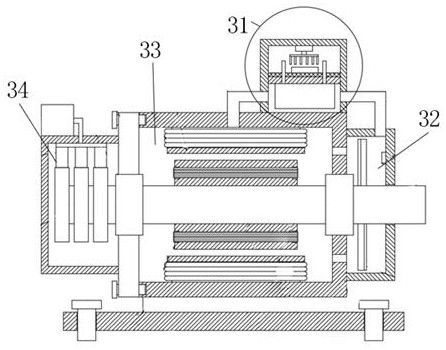
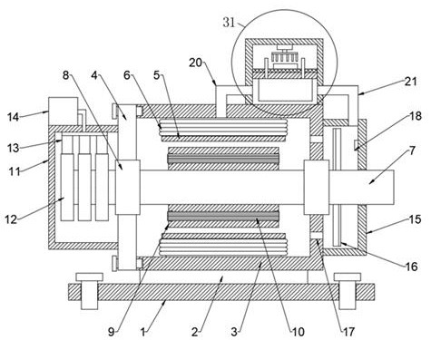
[0038] This embodiment provides a new energy vehicle motor, refer to figure 1 and 2 , this embodiment includes a first conduit 20 , a second conduit 21 , a temperature control module 31 , a circulation module 32 , a rotating module 33 and a rotating shaft 7 .

[0039] refer to figure 2 , the circulation module 32 includes the casing 15 and the fan blade 16 . The casing 15 is provided with a fan blade 16, the fan blade 16 is mounted on the rotating shaft 7, the rotating shaft 7 movably runs through the rotating module 33, the rotating module 33 is provided with a through hole 17, and the through hole 17 communicates with the rotating mold The cavity of group 33 and the cavity of housing 15.

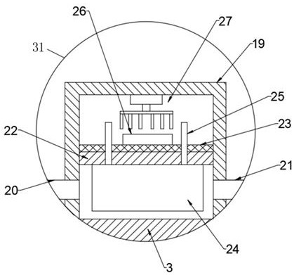
[0040] refer to image 3 , the temperature control module 31 includes the partition 22 , the temperature control plate 24 , the antifreeze, the box 19 and the temperature control module 26 . The partition 22 divides the box body 19 into an upper cavity and a lower cavity. Both sides...

Embodiment 2

[0045] On the basis of Embodiment 1, the new energy vehicle motor of this embodiment further includes a base plate 1 and a support block 2. During application, a bearing 8 is provided on the outer periphery of the rotating shaft 7, and the rotating shaft 7 is rotatably connected to the rotating module 33 through the bearing 8 , the rotating module 33 is installed on the support block 2 , and the support block 2 is installed on the base plate 1 .

[0046] The new energy vehicle motor in this embodiment further includes a control unit 14 and a brush module 34 , and introduces the rotation module 33 , the brush module 34 , the temperature control module 31 and the circulation module 32 in detail.

[0047] refer to figure 2 , the brush module 34 includes the housing 11 , the collector ring 12 and the brush 13 .

[0048] The control unit 14 is provided on the housing 11 , and the control unit 14 is connected to the brush 13 , so that the brush 13 is energized.

[0049] refer to ...


PUM


Abstract

The invention discloses a new energy automobile motor which comprises a first guide pipe, a second guide pipe, a temperature control module, a circulating module, a rotating module and a rotating shaft. The circulating module comprises a shell and fan blades; the shell is internally provided with fan blades, the fan blades are installed on the rotating shaft, the rotating shaft movably penetrates through the rotating module, the rotating module is provided with a through hole, and the through hole communicates with the rotating module and the shell; the temperature control module comprises a partition plate, a temperature adjusting plate, an anti-freezing solution, a box body and a temperature control module; the partition plate divides the box body into an upper cavity and a lower cavity; two sides of the lower cavity are respectively connected with a first conduit and a second conduit; the first guide pipe is communicated with the lower cavity and the rotating module; the second guide pipe is communicated with the lower cavity and the shell; a temperature adjusting plate is arranged in the lower cavity, a temperature guide rod is arranged on the temperature adjusting plate and penetrates through the partition plate to be connected with an anti-freezing solution, the upper cavity is filled with the anti-freezing solution, and a temperature control module is arranged in the upper cavity. According to the invention, gas circulation flow in the motor can be realized, and the gas temperature is adjusted, so that each element works in an optimal temperature environment.

Description

technical field [0001] The invention relates to the technical field of new energy vehicle motors, in particular to a new energy vehicle motor. Background technique [0002] Compared with traditional vehicles, new energy vehicles have less environmental pollution and have a huge application market. The on-board power supply of new energy vehicles provides electrical energy for the motor, which converts the electrical energy into mechanical energy and drives the transmission or directly drives the wheels to drive the car. [0003] At present, the temperature adjustment in the motor of new energy vehicles mainly depends on the fan at the rear end. The communication between the fan and the motor will accelerate the oxidation inside the motor, otherwise the effect of rapid cooling cannot be achieved. rising demand. [0004] Therefore, the present application proposes a new energy vehicle motor. SUMMARY OF THE INVENTION [0005] The purpose of the present invention is to over...

Claims


Application Information

Patent Timeline
IPC IPC(8): B60K1/00B60K11/06
CPCB60K1/00B60K11/06B60K2001/006B60K2001/008Y02T10/64
Inventor 王红然王彬彬许秀雯
Owner NANJING COLLEGE OF INFORMATION TECH
Why Eureka
Try Eureka