Bridge movable joint device and construction method

A technology of movable joints and construction methods, which can be used in bridges, bridge materials, bridge construction, etc., and can solve problems such as short bridge life.

Pending Publication Date: 2022-05-27
ZHEJIANG PROVINCIAL INST OF COMM PLANNING DESIGN & RES CO LTD
View PDF0 Cites 0 Cited by
  • Summary
  • Abstract
  • Description
  • Claims
  • Application Information

AI Technical Summary

Problems solved by technology

[0004] The purpose of the embodiments of the present application is to provide a bridge movable joint device and construction method, which aims to improve the problem of short bridge life in the related art

Method used


Image

  • Bridge movable joint device and construction method
  • Bridge movable joint device and construction method
  • Bridge movable joint device and construction method

Examples


Embodiment

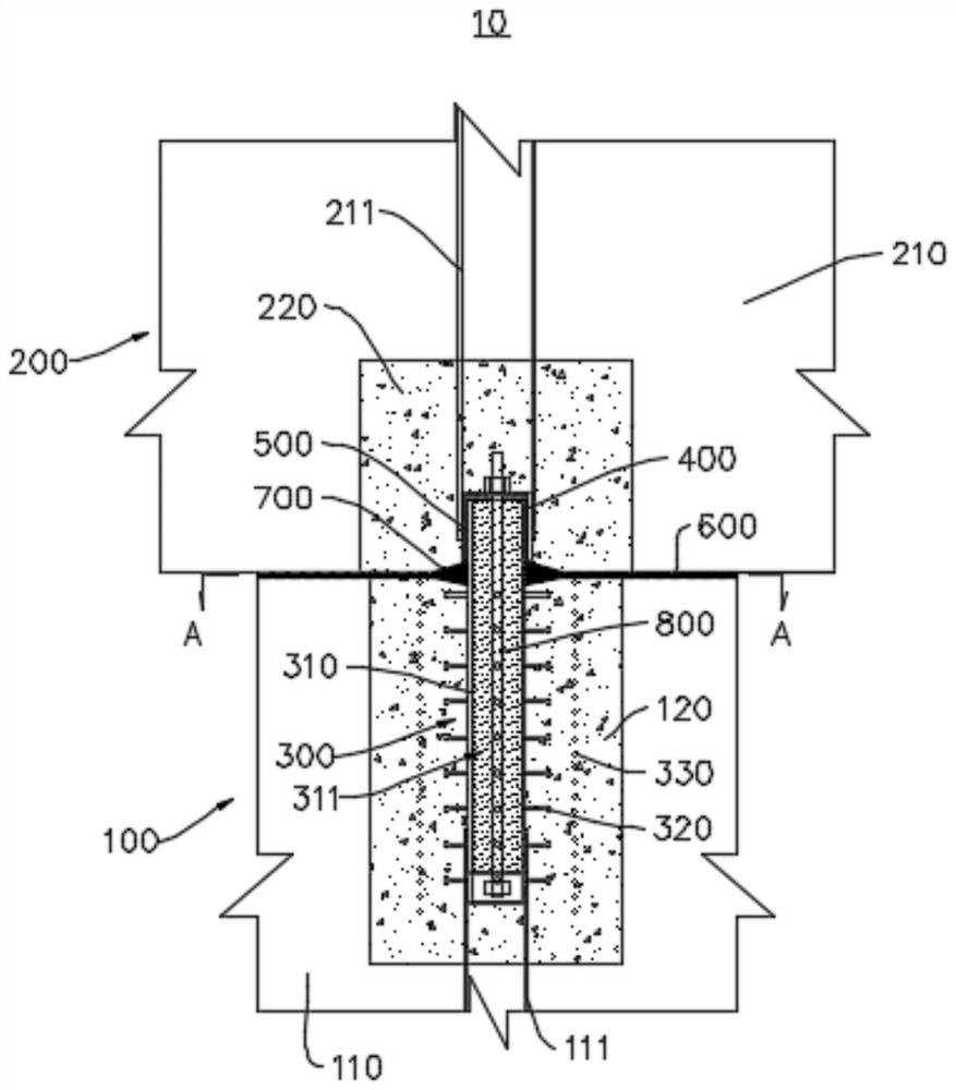
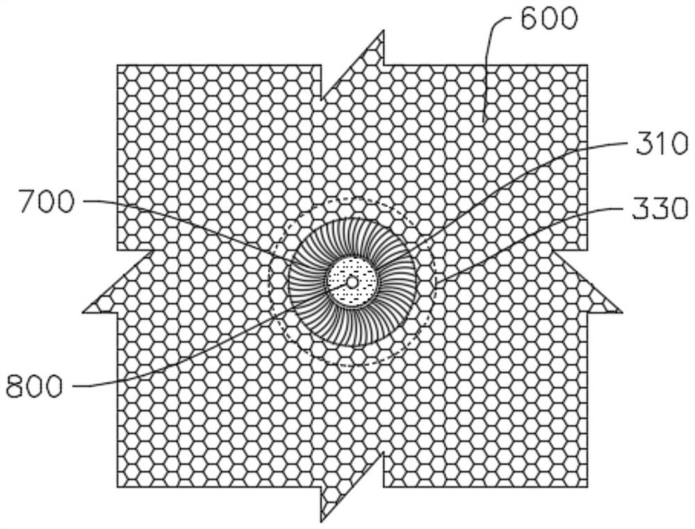
[0036] Please refer to figure 1The present embodiment provides a bridge movable joint device 10 . The bridge movable joint device 10 includes a first structural member 100 , a second structural member 200 , a joint head 300 , a joint socket 400 and a first elastic member 500 . The second structural member 200 is disposed on top of the first structural member 100 . The joint head 300 is connected to the first structural member 100 . The joint socket 400 is covered at one end of the joint head 300 , the joint socket 400 is connected with the second structural member 200 , and a joint cavity is formed between the joint head 300 and the joint socket 400 . The first elastic member 500 is disposed in the joint cavity, and the first elastic member 500 is configured to allow the joint head 300 to move relative to the joint socket 400 .

[0037] The bridge movable joint device 10 is connected with the first structural member 100 through the joint head 300, and is connected with the s...


PUM


Abstract

The invention provides a bridge movable joint device and a construction method, and relates to the field of bridge engineering. The bridge movable joint device comprises a first structural part, a second structural part, a joint head, a joint fossa and a first elastic part. The second structural member is arranged on the top of the first structural member. The joint head is connected with the first structural part. The articular fossa cover is arranged at one end of the articular head, and the articular fossa is connected with the second structural member. A joint cavity is formed between the joint head and the joint fossa. The first elastic piece is arranged in the articular cavity, and the first elastic piece is configured to allow the articular head and the articular fossa to move relatively. According to the bridge movable joint device, the joint head is connected with the first structural part, the joint nest is connected with the second structural part, the first elastic part is arranged between the joint head and the joint nest, and the first structural part can move relative to the second structural part, so that the bending moment and torque of the first structural part and the second structural part are released, and the structural stress is improved; the service life of the bridge is prolonged.

Description

technical field [0001] The present application relates to the field of bridge engineering, and in particular, to a bridge movable joint device and a construction method. Background technique [0002] A bridge generally refers to a structure erected on rivers, lakes and seas to enable vehicles and pedestrians to pass smoothly. In order to adapt to the modern and fast-developing transportation industry, bridges are also extended to bridges over mountain streams, unfavorable geology or other traffic needs to be erected to make traffic more convenient. [0003] At present, in the construction of bridges, rigid connections are often sampled, which leads to the difficulty in releasing the bending moment and torque of the bridge, and the short life of the bridge. SUMMARY OF THE INVENTION [0004] The purpose of the embodiments of the present application is to provide a bridge movable joint device and a construction method, which are aimed at improving the problem of short bridge...

Claims


Application Information

Patent Timeline
Patent Type & Authority Applications(China)
IPC IPC(8): E01D19/00E01D19/04E02D27/14E02D27/42E01D101/24E01D101/26
CPCE01D19/00E01D19/042E01D19/041E02D27/14E02D27/42E01D2101/24E01D2101/26E02D2600/20
Inventor 王昌将李闯石兆敏胡祥森黄亮戴少东余茂峰
Owner ZHEJIANG PROVINCIAL INST OF COMM PLANNING DESIGN & RES CO LTD
Why Eureka
Try Eureka