Direct-current brushless motor of electric tool

A brushless DC motor and power tool technology, applied in electric components, electromechanical devices, electrical components, etc., can solve the problems of complex production, low efficiency, large torque of the outer rotor structure, etc., and achieve the effect of improving the output ratio

Pending Publication Date: 2022-05-27
ZHEJIANG MINLI POWER TOOLS CO LTD
View PDF0 Cites 0 Cited by
  • Summary
  • Abstract
  • Description
  • Claims
  • Application Information

AI Technical Summary

Problems solved by technology

The structure of the outer rotor is rarely used due to the complex production and low efficiency, but the structure of the outer rotor has a large torque, which is not satisfied by the structure of the inner rotor.

Method used


Image

  • Direct-current brushless motor of electric tool
  • Direct-current brushless motor of electric tool
  • Direct-current brushless motor of electric tool

Examples


Embodiment 1

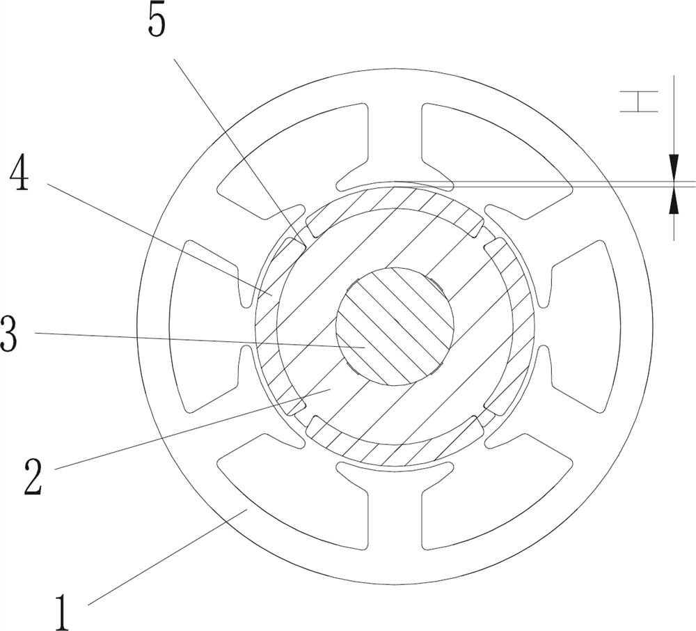
[0022] like figure 1 As shown in the figure, a brushless DC motor of an electric tool is used for the operation of non-magnetic materials to be processed, and specifically includes: a stator 1 for fixing on the inner wall of the electric tool casing, and a stator 1 sleeved However, the rotor cores 2 are not in contact with each other. The rotor core 2 is composed of silicon steel sheets. The stator 1 includes a stator core and a stator winding. A rotating shaft 3 is installed on the rotor core 2. The rotating shaft 3 passes through The bearing is fixed on the body of the electric tool. Further, the peripheral outer wall of the rotor core 2 is provided with a plurality of dovetail arc grooves 4, and the arc magnetic steel 5 is fixedly installed on the dovetail arc groove 4, so that it cannot follow the diameter of the rotor core 2. to disengage. Preferably, the angle between one side of the dovetail arc groove 4 is 80°. In this way, the minimum gap H between the arc-shaped m...

Embodiment 2

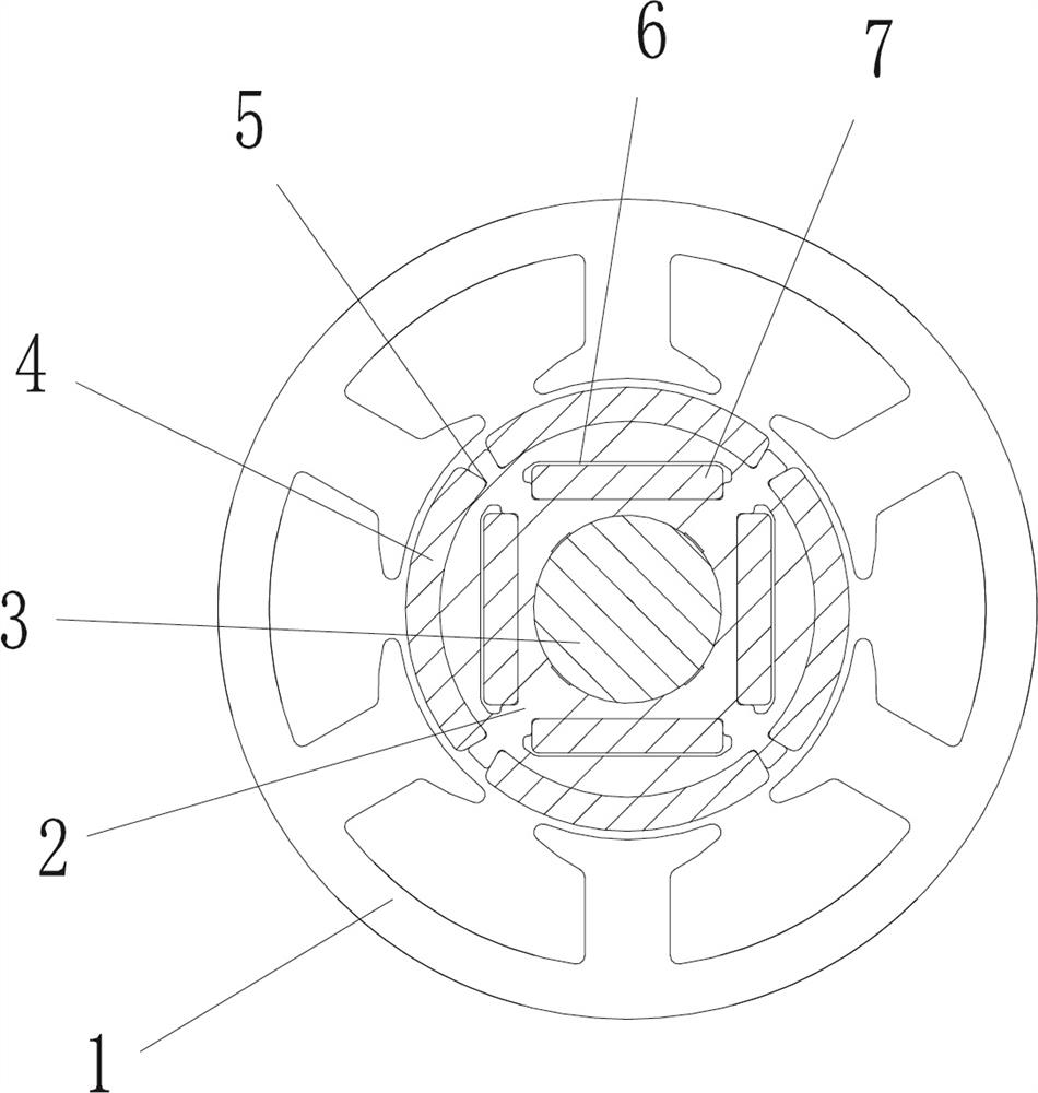
[0024] like figure 2 As shown, this embodiment further proposes a reinforced rotor structure. Specifically, on the basis of implementation 1, the rotor core 2 is further provided with a plurality of second limit slots 6. The second limit A rectangular magnetic steel 7 is arranged in the slot 6 , and the rectangular magnetic steel 7 is located between the rotating shaft 3 and the arc-shaped magnetic steel 5 . Preferably, the number of rectangular magnetic steels 5 is 4 and uniformly distributed in a ring shape, forming a substantially square shape that is not in contact. Similarly, according to the torque formula M=F1×L1+F2×L2, the torque can be increased by at least 25% under the condition of the same diameter rotor.

Embodiment 3 Embodiment 4

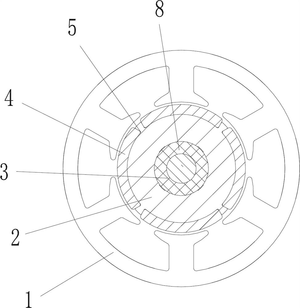
[0026] In the motor used in electric tools, ineffective eddy current will be generated during the operation of the motor, and the eddy current will generate ineffective heat, which will lead to abnormal heat generated by the motor. After the motor heats to a certain extent, the efficiency will drop or the insulating layer will be damaged, reducing the load resistance of the motor. . In order to overcome this defect, on the basis of implementing the first and second embodiments, such as Figure 3-4 As shown, the third embodiment and the fourth embodiment are further proposed, and a fixed insulating layer 8 is respectively provided between the rotating shaft 3 and the rotor core 2 .

[0027] According to the above, no matter which method is adopted, the torque of the motor and the output ratio of the motor have been increased. If the cost needs to be reduced, according to the torque formula M value under the same conditions as the existing inner rotor in the market, the perform...


PUM


Abstract

The invention discloses a direct current brushless motor of an electric tool, which comprises a stator fixed on the inner wall of a casing of the electric tool and a rotor core sleeved by the stator but not in contact with the stator, a rotating shaft is mounted on the rotor core, and the rotating shaft is fixed on a machine body of the electric tool through a bearing. Furthermore, a plurality of dovetail arc-shaped grooves are formed in the circumferential outer wall of the rotor core, and arc-shaped magnetic steel is fixedly installed on the dovetail arc-shaped grooves, so that the arc-shaped magnetic steel cannot be disengaged in the radial direction of the rotor core. Furthermore, a plurality of second limiting grooves can be formed in the rotor iron core, rectangular magnetic steel is arranged in the second limiting grooves, and the rectangular magnetic steel is located between the rotating shaft and the arc-shaped magnetic steel. According to the direct-current brushless motor of the electric tool provided by the invention, the torque of the motor can be improved as much as possible under the conditions of low cost and simple structure and process, and the output power ratio of the motor is improved.

Description

technical field [0001] The invention relates to the technical field of motors, in particular to a brushless DC motor of an electric tool. Background technique [0002] The brushless motors currently used in power tools are generally of an inner rotor or an outer rotor structure. The outer rotor structure is rarely used due to complex production and low efficiency, but the outer rotor structure has a large torsion, which is the inability of the inner rotor structure. The common inner rotor is embedded in the iron core composed of silicon steel sheets of the rotor, and the distance from the inner edge of the stator is far away, which leads to the farther distance of the rotor. It is well known that the torque of the motor is generated by cutting the magnetic field lines of the rotor. The inner edge of the stator, the smaller the cutting force. SUMMARY OF THE INVENTION [0003] Aiming at the deficiencies of the prior art, the present invention provides a DC brushless motor ...

Claims


Application Information

Patent Timeline
Patent Type & Authority Applications(China)
IPC IPC(8): H02K1/2706H02K1/274H02K1/28H02K29/00
CPCH02K1/2706H02K1/274H02K1/28H02K29/00H02K2213/03
Inventor 徐峰朱明亮王广平胡俊胡帅
Owner ZHEJIANG MINLI POWER TOOLS CO LTD
Why Eureka
Try Eureka