
Injection molding system

A technology of injection molding and injection port, which is applied in the field of injection molding systems, can solve the problems of poor appearance and poor molding of injection molded products, and achieve the effects of inhibiting poor molding, inhibiting the formation of resin coatings, and improving the inhibitory effect

Pending Publication Date: 2022-05-27
TOYO SEIKAN KAISHA LTD
View PDF3 Cites 0 Cited by
  • Summary
  • Abstract
  • Description
  • Claims
  • Application Information

AI Technical Summary

Problems solved by technology

[0003] However, during the cooling process after injecting the molten resin into the mold, the molten resin solidifies on the inner peripheral surface of the gate near the discharge port, etc., thereby forming a resin film, which may cause poor appearance of the injection molded product.
Conventional valve gate devices have no means to effectively solve molding defects caused by peeling of the resin film, so countermeasures are required

Method used


Image

  • Injection molding system
  • Injection molding system
  • Injection molding system

Examples


Embodiment approach

[0027] Hereinafter, preferred embodiments of the present invention will be described with reference to the drawings and the like.

[0028] (Structure related to the helical groove 41 of the shaft 40)

[0029] First, the structure, action, effect, and the like related to the helical groove 41 of the shaft 40 will be described.

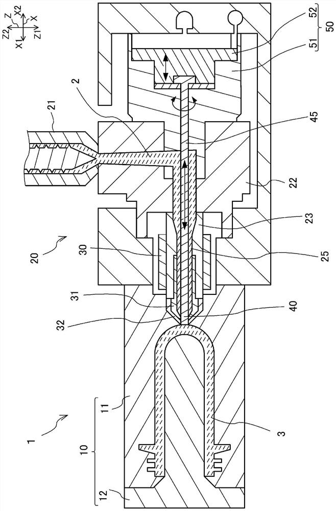
[0030] figure 1 It is a longitudinal cross-sectional view explaining the whole structure of the molding system 1 of embodiment.

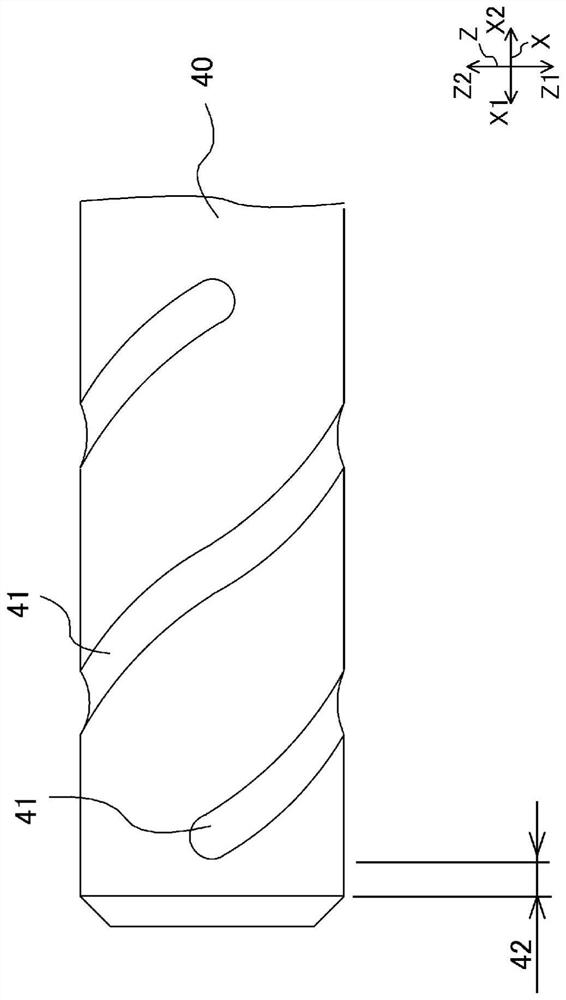
[0031] figure 2 This is an external view of the vicinity of the distal end of the shaft 40 .

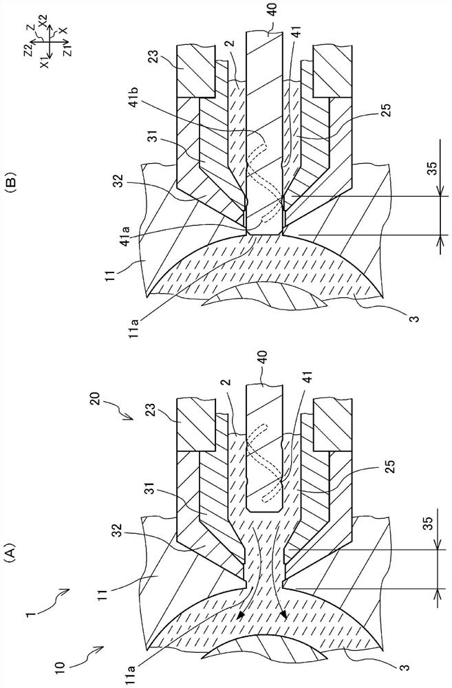
[0032] image 3 It is a longitudinal cross-sectional view explaining the structure of the connection hole 35 vicinity of the molding system 1 of embodiment.

[0033] image 3 (A) is a diagram explaining a state in which the tip of the shaft 40 is retracted / receded from the connection hole 35 and a state in which the molten resin is injected into the mold.

[0034] image 3 (B) is a diagram illustrating a state in which the ...


PUM


Abstract

The invention provides an injection molding system capable of suppressing poor molding caused by a resin coating formed in a flow path of molten resin. A shaft (240) of an injection molding system (1) is attached to a connection hole (35) for connecting a flow path (25) of an injection molding machine and an injection port (11a) for injecting molten resin into a mold (10), and is provided so as to be movable between a closed position for closing the injection port (11a) and an open position for opening the injection port (11a) at a position retracted from the closed position to the flow path (25) side. The spiral groove (241) is used for connecting a gap (S) between the connecting hole (35) and the shaft rod (240) and the flow channel (25) in a state that the spiral groove (241) is arranged at the closed position, and the peripheral groove (243) is arranged on the injection port (11a) side of the spiral groove (241).

Description

technical field [0001] The present invention relates to an injection molding system provided with an opening and closing pin. Background technique [0002] Conventionally, there has been a valve gate device that opens and closes a gate by inserting and extracting a gate opening and closing pin with respect to a discharge port (for example, Patent Document 1). [0003] However, during cooling after the molten resin is injected into the mold, the molten resin solidifies on the inner peripheral surface of the gate near the discharge port, etc., thereby forming a resin coating, which may cause poor appearance of the injection-molded product. Conventional valve gate apparatuses have no means for effectively solving molding failures caused by peeling of the resin coating or the like, and therefore countermeasures are desired. [0004] prior art literature [0005] Patent Literature [0006] Patent Document 1: Japanese Patent Laid-Open No. 2017-144631 SUMMARY OF THE INVENTION ...

Claims


Application Information

Patent Timeline
Patent Type & Authority Applications(China)
IPC IPC(8): B29C45/28
CPCB29C45/28
Inventor 田岛伴成竹谷雄太田所洋一栗原友纪
Owner TOYO SEIKAN KAISHA LTD
Learn More